Assembly settings
Product range
Immediately available
No
no
choose ...
Front
Front form
Round
Round
choose ...
Front bezel colour
Black
Black
choose ...
Front bezel material
Plastic
Plastic
choose ...
Front dimension
Ø 29 mm
Ø 29 mm
choose ...
Mounting
Design
Raised
Raised
choose ...
Mounting type
Panel mounting
Panel mounting
choose ...
Mounting cut-out
Ø 22 mm
Ø 22 mm
choose ...
Operating-/Indication part
Lens type
Raised above front bezel
Raised above front bezel
choose ...
Lens shape
Flush
Flush
choose ...
Lens colour
Blue
Blue
choose ...
Lens material
Plastic
Plastic
choose ...
Lens illumination
Illuminated
Illuminated
choose ...
Shape of illumination
Front
Front
choose ...
Illumination colour
Blue
Blue
choose ...
Marking plate illumination
illuminative
illuminative
choose ...
Electrical characteristics
Contacts configuration
1 NO
1 NO
choose ...
Switching rating
42 V @ 0,1 A
42 V @ 0,1 A
choose ...
Operating voltage kind of
V AC/DC
V AC/DC
choose ...
Operating voltage
24 V
24 V
choose ...
Mechanical Characteristics
Terminal
Universal terminal, 2 x 0.5 mm
Universal terminal, 2 x 0.5 mm
choose ...
Switching system
Low-level element
Low-level element
choose ...
Contact material
Gold
Gold
choose ...
Switching action
Momentary
Momentary
choose ...
Ambient Condition
IP front protection
IP67
IP67
choose ...
Back
Illuminated push button, Series 14, Ø 29 mm, illuminative, Raised, 1 NO, Gold, IP67, Universal terminal, 2 x 0.5 mm
- 704.611.6
- 704.610.9
- 14-435.036
- 704.600.0
- 10-2112.1066
- Marking plate illumination
- Lens type
- Lens colour
- Terminal
- Switching system
- Switching rating
- Switching action
- Contacts configuration

- Front bezel colour
- Front bezel material

- Illumination colour
- Operating voltage

Add Accessories & Tools
Your product:
Product range
- HMI function:
- Illuminated push button
- Series:
- Series 14
Front
- Front dimension:
- Ø 29 mm
- Front form:
- Round
- Front bezel colour:
- Black
- Front bezel material:
- Plastic
Mounting
- Design:
- Raised
- Mounting cut-out:
- Ø 22.5 mm
- Mounting type:
- Panel mounting
Operating-/Indication part
- Lens colour:
- Blue
- Lens material:
- Plastic
- Lens illumination:
- Illuminated
- Lens shape:
- Flush
- Lens optics:
- transparent
- Lens type:
- Raised above front bezel
- Marking plate illumination:
- illuminative
- Marking cap colour:
- White
- Illumination colour:
- Blue
- Shape of illumination:
- Front
Electrical characteristics
- Switching voltage and switching current:
- 100 mA at 42 VAC/VDC
- Contacts configuration:
- 1 NO
- Operating voltage:
- 24 V AC/DC +10%
- Operation current:
- 7 - 14 mA ±15 %
- Switching rating:
- 42 V @ 0,1 A
- Lumi. Intensity:
- 650 mcd
Mechanical Characteristics
- Terminal:
- Universal terminal, 2 x 0.5 mm
- Contact material:
- Gold
- Switching action:
- Momentary
- Switching system:
- Low-level element
- Tightening torque:
- Fixing nut max. 0.25 Nm
- Total weight:
- 0.022 kg
Ambient Condition
- IP front protection:
- IP67
- Operating temperature:
- – 25 °C … + 55 °C, mounted as a block, make sure the heat can escape freely
Other
- Housing colour:
- Black
- Wiring diagrams:
Share and save this product
Download files
Add to Cart
Your product consists of the following 5 COMPONENTS:

Front
- Front form:
- Round
Operating-/Indication part
- Lens colour:
- Blue
- Lens material:
- Plastic
- Lens illumination:
- Illuminated
- Lens shape:
- Flush
- Lens optics:
- transparent
- Lens type:
- Raised above front bezel
- Marking plate illumination:
- illuminative
- Shape of illumination:
- Front
Mechanical Characteristics
- Weight:
- 0.002 kg
Certificate
- REACH:
- REACH compliant
- RoHS:
- RoHS compliant
Other
- Short Description:
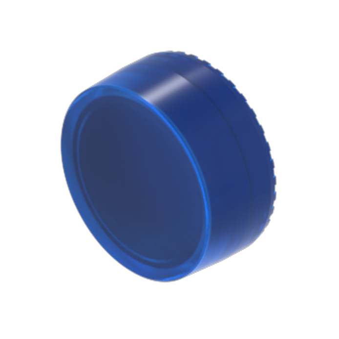
- Lens, Ø 23.7 mm, Illuminated, Blue, Flush, Plastic
- Dimension:
- Ø 23.7 mm
- Hints:
- To obtain IP67, use marking plate Part Nr. 704.610.X
Download files
Where to buy
Add to Cart

Operating-/Indication part
- Marking cap colour:
- White
- Marking cap optics:
- translucent
Mechanical Characteristics
- Weight:
- 0.001 kg
Certificate
- REACH:
- REACH compliant
- RoHS:
- RoHS compliant
Other
- Short Description:
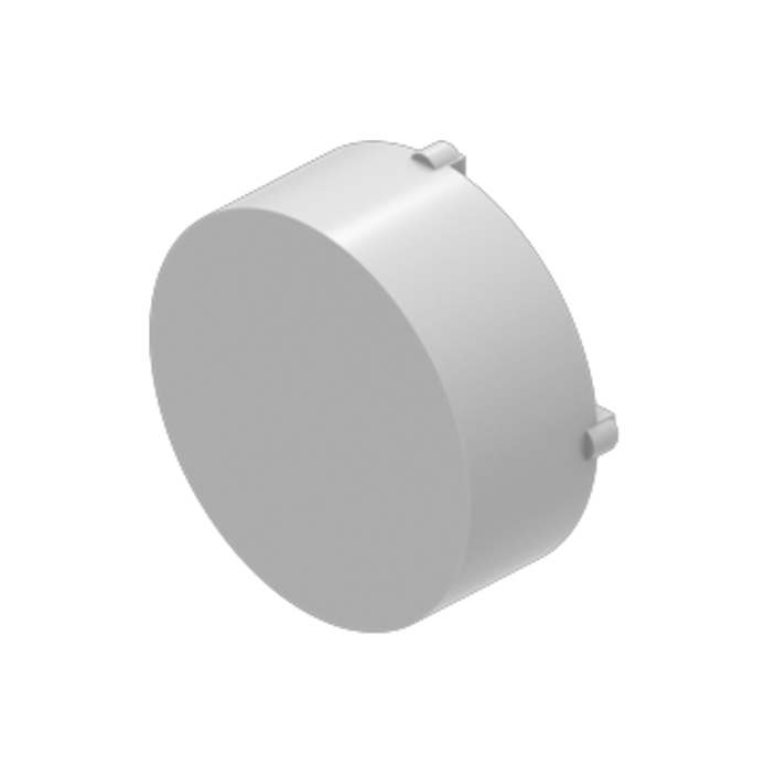
- Marking cap, LED and incandescent lamp, White, Plastic, translucent, Ø 29 mm
- Dimension:
- Ø 29 mm
Download files
Where to buy
Add to Cart

Front
- Front form:
- Round
Mounting
- Mounting type:
- Panel mounting
Operating-/Indication part
- Lens illumination:
- Illuminated
Electrical characteristics
- Switching voltage and switching current:
- 100 mA at 42 VAC/VDC
- Contacts:
- 1 NO
- Switching rating:
- 42 V @ 0,1 A
- Electric strength:
- 3000 VAC, 50 Hz, 1 min. between all terminals and earth, according to EN/IEC 61058-1
- Protection class:
- ll
Mechanical Characteristics
- Terminal:
- Universal terminal, 2 x 0.5 mm
- Contact material:
- Gold
- Switching action:
- Momentary
- Switching system:
- Low-level element
- Switching system:
- This low-level switching element was designed for switching low powers in electronic circuits. The mechanism assures reliable switching of loads ranging from a few μA/μV up to 100 mA/ 42 VAC/DC.Single-break momentary contact, as normally open or normally closed with 4 independent points of contact. 2 momentary contactsper switching element; combination of normally open and normally closed is possible.Special features are the long life, extremely short rebound time and stable contact resistance.
- Mechanical lifetime:
- 5 Mil. cycles of operation
- Operating force:
- 3 N … 4 N, depending on the number of switching elements
- Operating Travel:
- 3 mm
- Tightening torque:
- Fixing nut max. 0.25 Nm
- Terminal details 1:
- The universal terminals permit these units to be mounted on printed circuit boards (PCB). These terminals can also be used as soldering or plug-in terminals.For these terminals we can also supply a plug-in base which, when soldered on to the board, enables the switch to be plugged in.
- Wire cross section:
- Max. wire diameter 2 wires of 1 mmMax. wire cross-section of stranded cable 2 x 0.75 mm²
- Weight:
- 0.016 kg
Ambient Condition
- IP front protection:
- IP67, according to DIN EN 60529
- Operating temperature:
- – 25 °C … + 55 °C, mounted as a block, make sure the heat can escape freely
- Storage temperature:
- – 40 °C … + 85 °C
- Shock resistance:
- Max. 150 m / s², pulse width 11 ms, 3-axis, (semi-sinusoidal as per EN IEC 60068-2-27)
Certificate
- Conformities:
- 2011 / 65 / EC (RoHS), 2014 / 35 / EU (LVD)
- REACH:
- REACH compliant
- RoHS:
- RoHS compliant
Other
- Short Description:
- Actuator, Illuminated, Round, 1 NO, Momentary, Universal terminal, 2 x 0.5 mm, IP67, according to DIN EN 60529
- Housing colour:
- Black
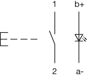
- Wiring diagrams:
- Component layouts:
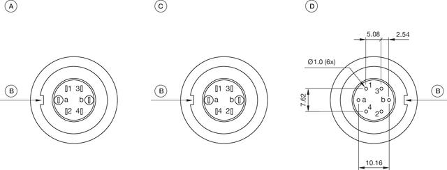 A = Terminals (rear side)
B = Anti twist device
C = Diode block
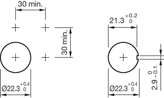
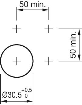
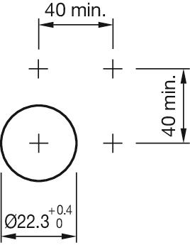
D = Drilling plan (component side)- Mounting cut-outs:

- Dimension drawings:
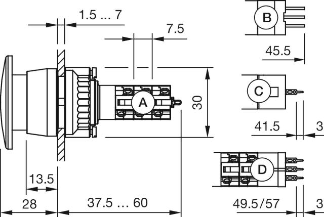 A = Solder terminal
B = Plug-in terminal 2.8 x 0.5 mm
C = Universal terminal 2.0 mm x 0.5 mm
D = Universal-Solder terminal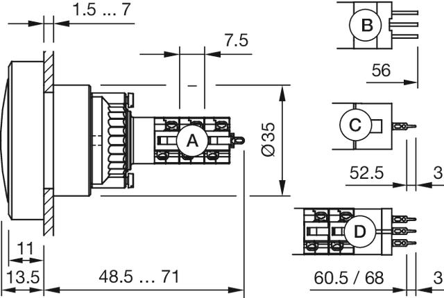 A = Solder terminal
B = Plug-in terminal 2.8 x 0.5 mm
C = Universal terminal 2.0 mm x 0.5 mm
D = Universal-Solder terminal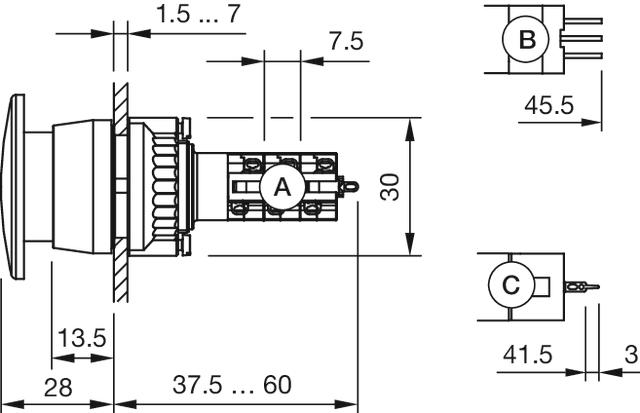 A = Solder terminal
B = Plug-in terminal 2.8 x 0.5 mm
C = Universal terminal 2.0 mm x 0.5 mm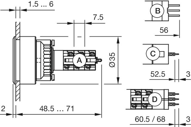 A = Solder terminal
B = Plug-in terminal 2.8 x 0.5 mm
C = Universal terminal 2.0 mm x 0.5 mm
Universal-Solder terminal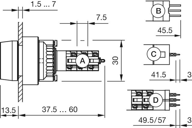 A = Solder terminal
B = Plug-in terminal 2.8 x 0.5 mm
C = Universal terminal 2.0 mm x 0.5 mm
D = Universal-Solder terminal
Download files
Where to buy
Add to Cart

Front
- Front dimension:
- Ø 29 mm
- Front form:
- Round
- Front bezel colour:
- Black
- Front bezel material:
- Plastic
Mounting
- Mounting type:
- Panel mounting
Mechanical Characteristics
- Weight:
- 0.002 kg
Certificate
- REACH:
- REACH compliant
- RoHS:
- RoHS compliant
Other
- Short Description:
- Front bezel, Ø 29 mm, Black, Plastic
- Dimension:
- Ø 29 mm
- Hints:
- The colour of anodised aluminium parts can vary due to technical production reasons
Download files
Where to buy
Add to Cart

Operating-/Indication part
- Illumination colour:
- Blue
Electrical characteristics
- Forward voltage:
- Operating voltage:
- 24 V AC/DC +10%
- Operation current:
- 7 - 14 mA ±15 %
- Lumi. Intensity:
- 650 mcd
Mechanical Characteristics
- Weight:
- 0.001 kg
Certificate
- REACH:
- REACH compliant
- RoHS:
- RoHS compliant
Other
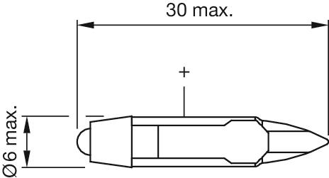
- Short Description:
- Single-LED, T5.6, Blue, 24 V AC/DC +10%
- Hints:
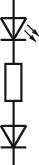
- For LED element fitting information see Application guidelines, LED polarityDue to high surface temperatures, the series resistor must not be soldered directly to the terminals of the equipment (use a terminal plate)When using AC/DC types with AC operation, slight flickering can occurThe luminous intensity stated is for when used with DCElectrical and optical data are measured at 25 °CThe specified versions are built with a protection diode (halve wave rectifier) in series and the LEDLuminosity and wave length variations caused by LED manufacturing processes may cause slight differences regarding the illumination. The customer has to decide what resistor shall be used to the LEDWhere supply voltages are over 48 V, a voltage-reduction element (external protective series resistor) must be used.
- Wiring diagrams:
- Dimension drawings:
Download files
Where to buy
Add to Cart