no
Round
Nature
Aluminium
Ø 29 mm
Raised
Panel mounting
Ø 22 mm
2 NC + 1 NO
500 V AC @ 10 A
Screw terminal
3 positions
Snap-action switching element
Palladium
Momentary - Rest (a) - Momentary
42° left / 42° right
IP65
Keylock switch, Series 04, Ø 29 mm, Raised, 2 NC + 1 NO, Screw terminal
- 704.115.0
- 704.902.5
- 704.902.2
- Switching angle
- Switching positions
- Front form
- Switching action
- Front dimension
- Front bezel colour
- Front bezel material

- Switching rating
- Terminal
- Contact material
- Switching system
- Contacts configuration

- Contact material
- Switching rating
- Terminal
- Switching system
- Contacts configuration

- HMI function:
- Key insert switch
- Series:
- Series 04
- Front dimension:
- Ø 29 mm
- Front form:
- Round
- Front bezel colour:
- Nature
- Front bezel material:
- Aluminium
- Design:
- Raised
- Mounting cut-out:
- Ø 22.5 mm
- Mounting type:
- Panel mounting
- Switching voltage and switching current:
as per DIN EN IEC 60947-5-1
voltage
DC13
AC15
24 V
2,5 A
60 V
0,8 A
110 V
0,6 A
120 V
4,5 A
230 V
0,2 A
4,5 A
400 V
0,15 A
4,0 A
500 V
0,7 A
2,5 A
as per UL 60947-5-1
voltage
power
24 VDC
2,5 A, Pilot duty
60 VDC
0,8 A, Pilot duty
120 VDC
0,6 A, Pilot duty
240 VDC
0,2 A, Pilot duty
415 VDC
0,15 A, Pilot duty
480 VDC
0,07A, Pilot duty
120 VAC
4,5 A, Pilot duty
240 VAC
4,5 A, Pilot duty
415 VAC
4,0 A, Pilot duty
480 VAC
2,5 A, Pilot duty
For voltages greater than Ue = 400 V,
the grid dimensions must not be
less than 35 mm x 50 mm.
- Contacts configuration:
- 2 NC + 1 NO
- Switching rating:
- 500 V AC @ 10 A
- Electrical lifetime:
- 50 000 cycles of operation
- Thermal current Ith:
- 10 A Max. permissible current for continuous operation and ambient temperatures not exceeding the specified max. values.
- Terminal:
- Screw terminal
- Contact material:
- Palladium
- Switching action:
- Momentary - Rest (a) - Momentary
- Switching system:
- Snap-action switching element
- Switching positions:
- 3 positions
- Switching angle:
- 42° left / 42° right
- Tightening torque:
- Screw terminal 0.5 Nm
- Total weight:
- 0.119 kg
- IP front protection:
- IP65
- Operating temperature:
- – 40 °C … + 55 °C
- Vibration resistance:
- 100 m/s² at 10 Hz … 500 Hz, amplitude 0.75 mm, (sinusoidal according to DIN EN 60068-2-6)
- max. number of switching elements:
- 3
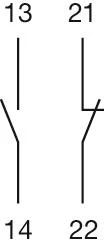
- Wiring diagrams:



- Front dimension:
- Ø 29 mm
- Front form:
- Round
- Front bezel colour:
- Nature
- Front bezel material:
- Aluminium
- Design:
- Raised
- Mounting type:
- Panel mounting
- Standards:
- The switches comply with the “Standards for low-voltage switching devices” DIN EN 60947-1
- Switching action:
- Momentary - Rest (a) - Momentary
- Switching positions:
- 3 positions
- Switching angle:
- 42° left / 42° right
- Mechanical lifetime:
- ≤50 000 cycles of operation
- Weight:
- 0.071 kg
- IP Protection:
- IP65 front side
- Operating temperature:
- – 40 °C … + 55 °C
- Storage temperature:
- – 40 °C … + 85 °C
- REACH:
- REACH compliant
- RoHS:
- RoHS compliant
- Short Description:
- Actuator, Ø 29 mm, Round, Nature, Aluminium, Momentary - Rest (a) - Momentary
- Hints:
- The standard lock Ronis 251Further lock numbers on requestMax. 3 switching elements can be clipped on
- max. number of switching elements:
- 3
- Switching positions:
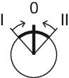
- Wiring diagrams:
- Mounting cut-outs:
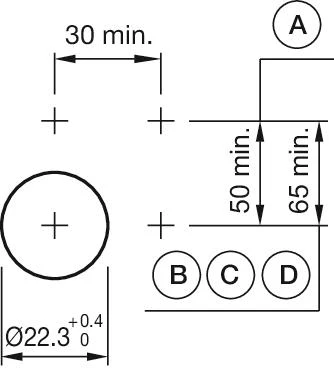 A = Screw terminal
B = Push-in terminal (PIT)
C = Plug-in terminal 6.3 mm x 0.8 mm
D = Double plug-in terminal 6.3 mm x 0.8 mm- Dimension drawings:
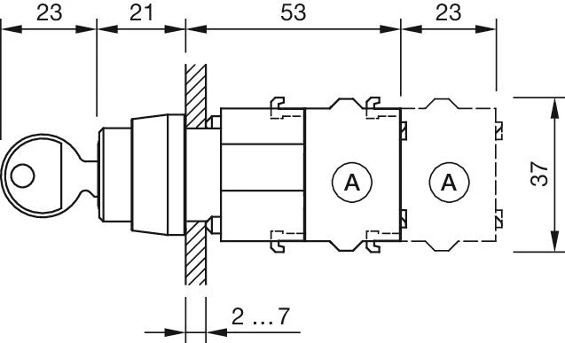 A = Screw terminal

- Switching voltage and switching current:
as per DIN EN IEC 60947-5-1
voltage
DC13
AC15
24 V
2,5 A
60 V
0,8 A
110 V
0,6 A
120 V
4,5 A
230 V
0,2 A
4,5 A
400 V
0,15 A
4,0 A
500 V
0,7 A
2,5 A
as per UL 60947-5-1
voltage
power
24 VDC
2,5 A, Pilot duty
60 VDC
0,8 A, Pilot duty
120 VDC
0,6 A, Pilot duty
240 VDC
0,2 A, Pilot duty
415 VDC
0,15 A, Pilot duty
480 VDC
0,07A, Pilot duty
120 VAC
4,5 A, Pilot duty
240 VAC
4,5 A, Pilot duty
415 VAC
4,0 A, Pilot duty
480 VAC
2,5 A, Pilot duty
For voltages greater than Ue = 400 V,
the grid dimensions must not be
less than 35 mm x 50 mm.
- Contacts:
- 1 NC / 1 NO
- Forward voltage:
- Rated impulse withstand voltage Uimp:
- 4 kV, according to EN/IEC 60947-5-1
- Rated insulation voltage Ui:
- 500 V
- Recommended minimum operational data:
Gold-silver contacts
Voltage
5 VDC
24 VDC
110 VDC
Current
15 mA
5 mA
2 mA
Hard silver contacts
Voltage
24 VDC
110 VDC
Current
50 mA
10 mA
- Switching rating:
- 500 V AC @ 10 A
- Electrical lifetime:
- 50 000 cycles of operation
- Pollution degree:
- 3
- Standards:
- The switches comply with the “Standards for low-voltage switching devices” EN IEC 60947-5-1
- Thermal current Ith:
- 10 A Max. permissible current for continuous operation and ambient temperatures not exceeding the specified max. values.
- Terminal:
- Screw terminal
- Contact material:
- Palladium
- Switching system:
- Snap-action switching element
- Switching system:
- The double-break, snap-action switching element is equipped with one or two independent contact systems, acting as normally open or normally closed contact. The snap-action switching element is fitted with self-cleaning contacts.
- Operating force:
- 1 Normally closed approx. 1.9 N, 1 Normally open approx. 2 N
- Tightening torque:
- Screw terminal 0.5 Nm
- Wire cross section:
- Max. wire cross-section 2 mm x 2.5 mm²Skinning wire 10 mmMax. wire cross-section of stranded cable 2 x 1.5 mm²use stranded wires only with wire end ferrules of 10 mm lengthOnly one polarity is allowed on each side when wiring.
- Weight:
- 0.028 kg
- IP Protection:
- IP00
- Operating temperature:
- – 40 °C … + 55 °C
- Storage temperature:
- – 40 °C … + 85 °C
- Shock resistance:
- 300 m/s², pulse width 11 ms, 3-axis, (single impacts, semi-sinusoidal as per DIN EN 60068-2-27)
- Vibration resistance:
- 100 m/s² at 10 Hz … 500 Hz, amplitude 0.75 mm, (sinusoidal according to DIN EN 60068-2-6)
- Climate resistance:
- Relative humidity, max. 95%, non-condensing
- Approbations:
- CB (IEC 60947-5-1), cULus, DNV, NFF, VDE
- Conformities:
- CE, CCC, UKCA
- REACH:
- REACH compliant
- RoHS:
- RoHS compliant
- Short Description:
- Switching element, Snap-action switching element, 500 V AC @ 10 A, Palladium, 1 NC / 1 NO, Screw terminal
- Hints:
- When using the switching element, the application guidelines must be observed.For the third switching element the terminal marking insert is to be ordered separatelyOperating temperature: Other temperatures on request
- Wiring diagrams:
- Dimension drawings:
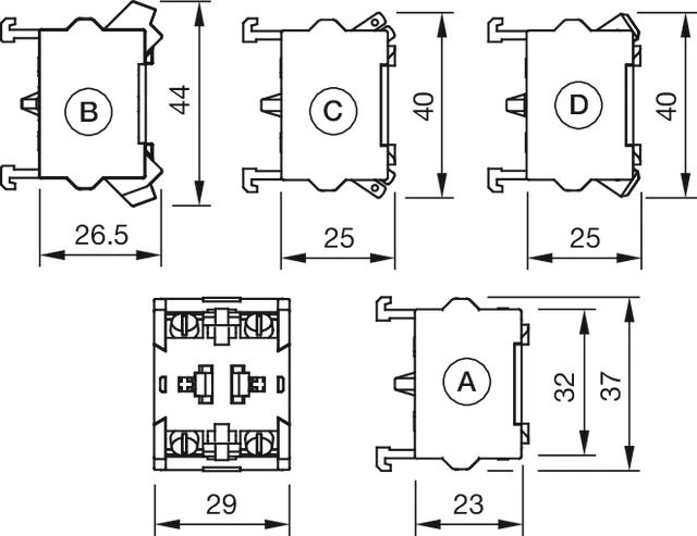 A = Screw terminal
B = Push-in terminal (PIT)
C = Plug-in terminal 6.3 mm x 0.8 mm
D = Double plug-in terminal 6.3 mm x 0.8 mm

- Switching voltage and switching current:
as per DIN EN IEC 60947-5-1
voltage
DC13
AC15
24 V
2,5 A
60 V
0,8 A
110 V
0,6 A
120 V
4,5 A
230 V
0,2 A
4,5 A
400 V
0,15 A
4,0 A
500 V
0,7 A
2,5 A
as per UL 60947-5-1
voltage
power
24 VDC
2,5 A, Pilot duty
60 VDC
0,8 A, Pilot duty
120 VDC
0,6 A, Pilot duty
240 VDC
0,2 A, Pilot duty
415 VDC
0,15 A, Pilot duty
480 VDC
0,07A, Pilot duty
120 VAC
4,5 A, Pilot duty
240 VAC
4,5 A, Pilot duty
415 VAC
4,0 A, Pilot duty
480 VAC
2,5 A, Pilot duty
For voltages greater than Ue = 400 V,
the grid dimensions must not be
less than 35 mm x 50 mm.
- Contacts:
- 1 NC
- Forward voltage:
- Rated impulse withstand voltage Uimp:
- 4 kV, according to EN/IEC 60947-5-1
- Rated insulation voltage Ui:
- 500 V
- Recommended minimum operational data:
Gold-silver contacts
Voltage
5 VDC
24 VDC
110 VDC
Current
15 mA
5 mA
2 mA
Hard silver contacts
Voltage
24 VDC
110 VDC
Current
50 mA
10 mA
- Switching rating:
- 500 V AC @ 10 A
- Electrical lifetime:
- 50 000 cycles of operation
- Pollution degree:
- 3
- Standards:
- The switches comply with the “Standards for low-voltage switching devices” EN IEC 60947-5-1
- Thermal current Ith:
- 10 A Max. permissible current for continuous operation and ambient temperatures not exceeding the specified max. values.
- Terminal:
- Screw terminal
- Contact material:
- Palladium
- Switching system:
- Snap-action switching element
- Switching system:
- The double-break, snap-action switching element is equipped with one or two independent contact systems, acting as normally open or normally closed contact. The snap-action switching element is fitted with self-cleaning contacts.
- Operating force:
- 1 Normally closed approx. 1.9 N, 1 Normally open approx. 2 N
- Tightening torque:
- Screw terminal 0.5 Nm
- Wire cross section:
- Max. wire cross-section 2 mm x 2.5 mm²Skinning wire 10 mmMax. wire cross-section of stranded cable 2 x 1.5 mm²use stranded wires only with wire end ferrules of 10 mm lengthOnly one polarity is allowed on each side when wiring.
- Weight:
- 0.02 kg
- IP Protection:
- IP00
- Operating temperature:
- – 40 °C … + 55 °C
- Storage temperature:
- – 40 °C … + 85 °C
- Shock resistance:
- 300 m/s², pulse width 11 ms, 3-axis, (single impacts, semi-sinusoidal as per DIN EN 60068-2-27)
- Vibration resistance:
- 100 m/s² at 10 Hz … 500 Hz, amplitude 0.75 mm, (sinusoidal according to DIN EN 60068-2-6)
- Climate resistance:
- Relative humidity, max. 95%, non-condensing
- Approbations:
- CB (IEC 60947-5-1), cULus, DNV, NFF, VDE
- Conformities:
- CE, CCC, UKCA
- REACH:
- REACH compliant
- RoHS:
- RoHS compliant
- Short Description:
- Switching element, Snap-action switching element, 500 V AC @ 10 A, Palladium, 1 NC, Screw terminal
- Hints:
- When using the switching element, the application guidelines must be observed.For the third switching element the terminal marking insert is to be ordered separatelyOperating temperature: Other temperatures on request
- Wiring diagrams:
- Dimension drawings:
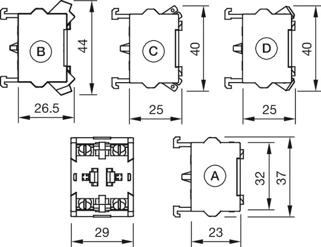 A = Screw terminal
B = Push-in terminal (PIT)
C = Plug-in terminal 6.3 mm x 0.8 mm
D = Double plug-in terminal 6.3 mm x 0.8 mm