Assembly settings
Product range
Immediately available
Yes
yes
choose ...
Front
Front form
Rectangular
Rectangular
choose ...
Front bezel colour
Black
Black
choose ...
Front bezel material
Plastic
Plastic
choose ...
Front dimension
24 mm x 18 mm
24 mm x 18 mm
choose ...
Mounting
Design
Raised
Raised
choose ...
Mounting type
Panel mounting
Panel mounting
choose ...
Mounting cut-out
Ø 16 mm
Ø 16 mm
choose ...
Mechanical Characteristics
Terminal
Plug-in terminal, 2.8 x 0.5 mm
Plug-in terminal, 2.8 x 0.5 mm
choose ...
Ambient Condition
IP front protection
IP40
IP40
choose ...
Back
Buzzer, Series 51, 24 mm x 18 mm, Raised, Plug-in terminal, 2.8 x 0.5 mm
- 51-801.002
- Terminal

Add Accessories & Tools
Your product:
Product range
- HMI function:
- Buzzer
- Series:
- Series 51
Front
- Front dimension:
- 24 mm x 18 mm
- Front form:
- Rectangular
- Front bezel colour:
- Black
- Front bezel material:
- Plastic
Mounting
- Design:
- Raised
- Mounting cut-out:
- Ø 16 mm
- Mounting type:
- Panel mounting
Mechanical Characteristics
- Terminal:
- Plug-in terminal, 2.8 x 0.5 mm
- Tightening torque:
- Fixing nut max. 0.5 Nm
- Total weight:
- 0.009 kg
Acoustical Characteristics
- Tone frequency:
- 2.1 kHz
- Sound pressure:
- 88dB (A) ±8dB at a distance of 0.1m
Ambient Condition
- IP front protection:
- IP40
- Operating temperature:
- – 25 °C … + 55 °C
Other
- Housing colour:
- Black
- Housing material:
- Plastic
- Product attributes:
- Further information see Technical data
- Wiring diagrams:
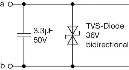 Recommended Protection Circuit: If the buzzer is not indirectly protected against surge impulses by an EMC-compliant power supply or if the cable length exceeds 30 m, additional protection measures are recommended. In this case, a bidirectional TVS diode should be installed between the connection wires as close to the buzzer as possible, as shown in the schematic above. To suppress conducted emissions, a ceramic capacitor of 3.3 µF / 50 V should additionally be connected at the buzzer terminals [a] and [b].
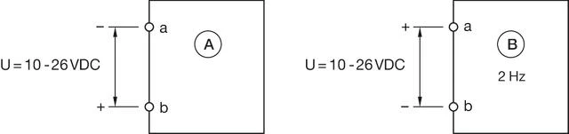 A = Continuous tone
B = Interval tone 2Hz
Share and save this product
Download files
Add to Cart
Your product consists of the following 1 COMPONENTS:

Front
- Front dimension:
- 24 mm x 18 mm
- Front form:
- Rectangular
- Front bezel colour:
- Black
- Front bezel material:
- Plastic
Mounting
- Design:
- Raised
- Mounting cut-out:
- Ø 16 mm
- Mounting type:
- Panel mounting
Electrical characteristics
- Operating Voltage and Current:
Typ. 10 VDC ... 26 VDC, ≤ 20mA
Mechanical Characteristics
- Terminal:
- Plug-in terminal, 2.8 x 0.5 mm
- Tightening torque:
- Fixing nut max. 0.5 Nm
- Weight:
- 0.009 kg
Acoustical Characteristics
- Tone frequency:
- 2.1 kHz
- Sound pressure:
- 88dB (A) ±8dB at a distance of 0.1m
Ambient Condition
- IP Protection:
- IP40
- Operating temperature:
- – 25 °C … + 55 °C
- Storage temperature:
- – 40 °C … + 85 °C
Certificate
- Approbations:
- DNV
- Conformities:
- CE, UKCA, 2011 / 65 / EC (RoHS), 2014 / 35 / EU (LVD)
- REACH:
- REACH compliant
- RoHS:
- RoHS compliant
Other
- Short Description:
- Actuator, Ø 16 mm, 24 mm x 18 mm, Rectangular, Black, Plastic, Plug-in terminal, 2.8 x 0.5 mm
- Housing colour:
- Black
- Housing material:
- Plastic
- Product attributes:
- Further information see Technical data
- Buzzer system:
- Electronic non-contacting buzzer with IC oscillator
- Wiring diagrams:
- Recommended Protection Circuit: If the buzzer is not indirectly protected against surge impulses by an EMC-compliant power supply or if the cable length exceeds 30 m, additional protection measures are recommended. In this case, a bidirectional TVS diode should be installed between the connection wires as close to the buzzer as possible, as shown in the schematic above. To suppress conducted emissions, a ceramic capacitor of 3.3 µF / 50 V should additionally be connected at the buzzer terminals [a] and [b].A = Continuous tone
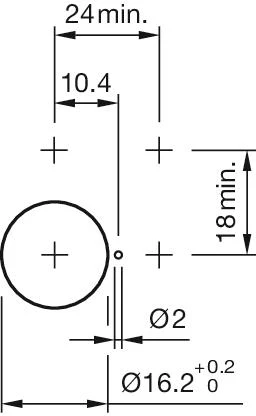
B = Interval tone 2Hz - Mounting cut-outs:
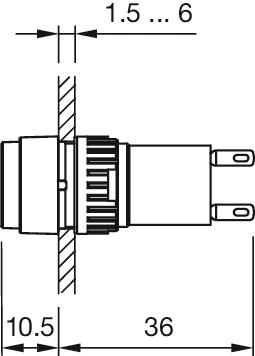
- Dimension drawings:
Download files
Where to buy
Add to Cart