no
Round
Black
Aluminium
Ø 35 mm
Flush
Panel mounting
Ø 30 mm
long
Black
translucent
Red / Yellow
1 NC + 1 NO
250 V AC @ 6 A
V DC
24 V
Push-in terminal
2 positions
Slow-make switching element
Gold
Rest - Maintained
90° right
IP65
Selector switch, Series 04, 2 positions, Flush, 1 NC + 1 NO, Push-in terminal
- 704.101.010I
- 704.950.3
- 10-2H12.314B
- 704.917.5
- Front form
- Lever shape
- Switching action
- Switching angle
- Front bezel colour
- Front dimension
- Front bezel material

- Terminal

- Operating voltage
- Operating voltage kind of
- Illumination colour

- Contact material
- Terminal
- Switching system
- Switching rating
- Contacts configuration

- HMI function:
- Selector switch
- Series:
- Series 04
- Front dimension:
- Ø 35 mm
- Front form:
- Round
- Front bezel colour:
- Black
- Front bezel material:
- Aluminium
- Design:
- Flush
- Mounting cut-out:
- Ø 30.5 mm
- Mounting type:
- Panel mounting
- Lever colour:
- Black
- Lever bar colour:
- translucent
- Lever shape:
- long
- Illumination colour:
- Red / Yellow
- Switching voltage and switching current:
as per DIN EN IEC 60947-5-1
voltage
DC13
AC15
24 V
4.0 A
8.0 A
60 V
1.5 A
8.0 A
110 V
1.0 A
120 V
8.0 A
230 V
0.4 A
7.0 A
400 V
0.2 A
5.0 A
500 V
0.15 A
4.0 A
as per UL 60947-5-1
voltage
power
24 VDC
4.0 A, Pilot duty
60 VDC
1.5 A, Pilot duty
120 VDC
1.0 A, Pilot duty
240 VDC
0.4 A, Pilot duty
415 VDC
0.2 A, Pilot duty
480 VDC
0.14A, Pilot duty
120 VAC
8.0 A, Pilot duty
240 VAC
7.0 A, Pilot duty
415 VAC
5.0 A, Pilot duty
480 VAC
4.0 A, Pilot duty
- Contacts configuration:
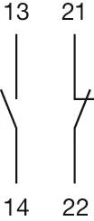
- 1 NC + 1 NO
- Operating voltage:
- 24 V DC +10%
- Operation current:
- 15 mA ±15 %
- Switching rating:
- 250 V AC @ 6 A
- Electrical lifetime:
- 50 000 cycles of operation
- Lumi. Intensity:
- 1200/550 mcd
- Thermal current Ith:
- 6 A 10 A Max. zulässiger Strom bei Dauerbetrieb und Umgebungstemperaturen, welche die angegebenen max. Werte nicht überschreiten. 10 A Max. permissible current for continuous operation and ambient temperatures not exceeding the specified max. values.
- Terminal:
- Push-in terminal
- Contact material:
- Gold
- Switching action:
- Rest - Maintained
- Switching system:
- Slow-make switching element
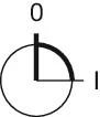
- Switching positions:
- 2 positions
- Switching angle:
- 90° right
- Total weight:
- 0.097 kg
- IP front protection:
- IP65
- Operating temperature:
- – 40 °C … + 55 °C
- Vibration resistance:
- Max. 100 m / s² from 10 Hz ... 500 Hz, (sinusoidal EN IEC 60068-2-6)
- Housing material:
- Plastic
- Product attributes:
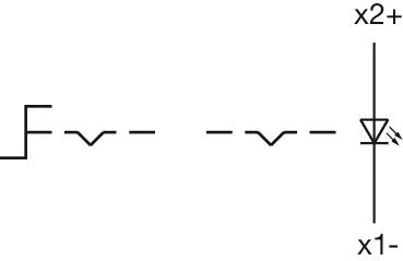
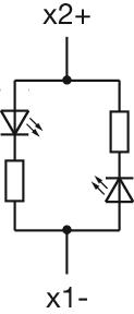
- X2: + = Red / X1: + = Yellow
- max. number of switching elements:
- 3
- Wiring diagrams:


- Front dimension:
- Ø 35 mm
- Front form:
- Round
- Front bezel colour:
- Black
- Front bezel material:
- Aluminium
- Design:
- Flush
- Mounting cut-out:
- Ø 30.5 mm
- Mounting type:
- Panel mounting
- Lever colour:
- Black
- Lever bar colour:
- translucent
- Lever material:
- plastic
- Lever shape:
- long
- Standards:
- The switches comply with the “Standards for low-voltage switching devices” DIN EN 60947-1
- Switching action:
- Rest - Maintained
- Switching positions:
- 2 positions
- Switching angle:
- 90° right
- Mechanical lifetime:
- ≤2.5 Mil. cycles of operation
- Weight:
- 0.052 kg
- IP Protection:
- IP65 front side
- Operating temperature:
- – 40 °C … + 55 °C
- Storage temperature:
- – 40 °C … + 85 °C
- REACH:
- REACH compliant
- RoHS:
- RoHS compliant
- Short Description:
- Actuator, Ø 30.5 mm, Ø 35 mm, optional illuminative, Black, long, Round, Black, Aluminium, anodised, Rest - Maintained
- Hints:
- Max. 3 switching elements can be clipped on
- max. number of switching elements:
- 3
- Switching positions:
- Wiring diagrams:
- Mounting cut-outs:
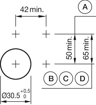 A = Screw terminal
B = Push-in terminal (PIT)
C = Plug-in terminal 6.3 mm x 0.8 mm
D = Double plug-in terminal 6.3 mm x 0.8 mm- Dimension drawings:
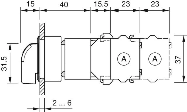 A = Screw terminal

- Standards:
- The switches comply with the “Standards for low-voltage switching devices” DIN EN 60947-1/DIN EN 60947-5-1
- Terminal:
- Push-in terminal
- Switching positions:
- 2 positions
- Wire cross section:
- Max. wire cross-section 2 wires with 1 mmSkinning wire 8 mmMax. wire cross-section of stranded cable 2 x 0.75 mm²use stranded wires only with wire end ferrules of 8 mm lengthOnly one polarity is allowed on each side when wiring.
- Weight:
- 0.015 kg
- IP Protection:
- IP20
- Operating temperature:
- – 40 °C … + 55 °C
- Storage temperature:
- – 40 °C … + 85 °C
- Shock resistance:
- Max. 300 m/s², pulse width 11 ms (sinusoidal EN IEC 60068-2-27)
- Vibration resistance:
- Max. 100 m / s² from 10 Hz ... 500 Hz, (sinusoidal EN IEC 60068-2-6)
- Climate resistance:
- Relative humidity, max. 95%, non-condensing
- REACH:
- REACH compliant
- RoHS:
- RoHS compliant
- Short Description:
- Lamp block, Plastic, Push-in terminal
- Housing material:
- Plastic
- Hints:
- When using the lamp block, the application guidelines must be observed.
- Wiring diagrams:
- Dimension drawings:
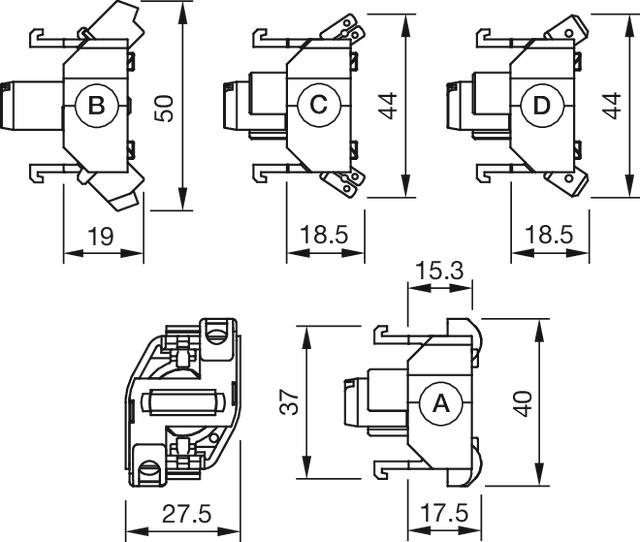 A = Screw terminal
B = Push-in terminal (PIT)
C = Plug-in terminal 6.3 mm x 0.8 mm
D = Double plug-in terminal 6.3 mm x 0.8 mm

- Illumination colour:
- Red / Yellow
- Forward voltage:
- Operating voltage:
- 24 V DC +10%
- Operation current:
- 15 mA ±15 %
- Lumi. Intensity:
- 1200/550 mcd
- Weight:
- 0.002 kg
- REACH:
- REACH compliant
- RoHS:
- RoHS compliant
- Short Description:
- Bi-colour LED, BA9s, Red / Yellow, 24 V DC +10%
- Kind of iIllumination:
- Bi-colour-LED
- Product attributes:
- X2: + = Red / X1: + = Yellow
- Hints:
- The max. overall length of the lamp may not exeed 25mmElectrical and optical data are measured at 25 °CThe specified 6 V DC, 24 V DC Bi-colour; 130 V AC, 130 V DC and 230 V AC versions are built with a protection diodeLuminosity and wave length variations caused by LED manufacturing processes may cause slight differences regarding the illumination. The customer has to decide what resistor shall be used to the LED
- Wiring diagrams:
- Dimension drawings:
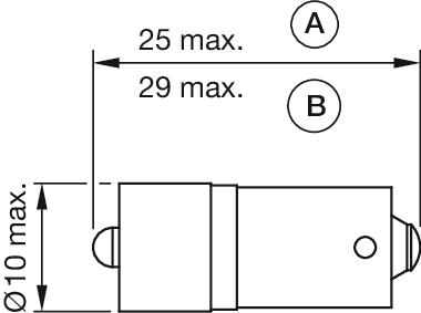 A = (standard)
B = (super bright)

- Switching voltage and switching current:
as per DIN EN IEC 60947-5-1
voltage
DC13
AC15
24 V
4.0 A
8.0 A
60 V
1.5 A
8.0 A
110 V
1.0 A
120 V
8.0 A
230 V
0.4 A
7.0 A
400 V
0.2 A
5.0 A
500 V
0.15 A
4.0 A
as per UL 60947-5-1
voltage
power
24 VDC
4.0 A, Pilot duty
60 VDC
1.5 A, Pilot duty
120 VDC
1.0 A, Pilot duty
240 VDC
0.4 A, Pilot duty
415 VDC
0.2 A, Pilot duty
480 VDC
0.14A, Pilot duty
120 VAC
8.0 A, Pilot duty
240 VAC
7.0 A, Pilot duty
415 VAC
5.0 A, Pilot duty
480 VAC
4.0 A, Pilot duty
- Contacts:
- 1 NC / 1 NO
- Forward voltage:
- Rated impulse withstand voltage Uimp:
- 4 kV, according to EN/IEC 60947-5-1
- Rated insulation voltage Ui:
- 500 V
- Recommended minimum operational data:
Gold-silver contacts
Voltage
24 VDC
Current
5 mA
Hard silver contacts
Voltage
24 VDC
Current
50 mA
- Switching rating:
- 250 V AC @ 6 A
- Electrical lifetime:
- 50 000 cycles of operation
- Pollution degree:
- 3
- Standards:
- The switches comply with the “Standards for low-voltage switching devices” EN IEC 60947-5-1
- Thermal current Ith:
- 6 A 10 A Max. zulässiger Strom bei Dauerbetrieb und Umgebungstemperaturen, welche die angegebenen max. Werte nicht überschreiten. 10 A Max. permissible current for continuous operation and ambient temperatures not exceeding the specified max. values.
- Terminal:
- Push-in terminal
- Contact material:
- Gold
- Switching system:
- Slow-make switching element
- Switching system:
- The double-break, slow-make switching element is equipped with one or two independent contact systems, acting as normally open or normally closed contact. The normally closed contact has forced opening.Slow-make contacts with forced action are ideal for high switch ratings.
- Operating force:
- 1 Normally closed approx. 2 N, 1 Normally open approx. 3 N
- Wire cross section:
- Max. wire cross-section 2 wires with 1 mmSkinning wire 8 mmMax. wire cross-section of stranded cable 2 x 0.75 mm²use stranded wires only with wire end ferrules of 8 mm lengthOnly one polarity is allowed on each side when wiring.
- Weight:
- 0.028 kg
- IP Protection:
- IP20
- Operating temperature:
- – 40 °C … + 55 °C
- Storage temperature:
- – 40 °C … + 85 °C
- Shock resistance:
- 300 m/s², pulse width 18 ms, (single impacts, semi-sinusoidal as per EN IEC 60068-2-27)
- Climate resistance:
- Relative humidity, max. 95%, non-condensing
- Approbations:
- CB (IEC 60947-5-1), cULus, DNV, NFF, VDE
- Conformities:
- CE, CCC, UKCA
- REACH:
- REACH compliant
- RoHS:
- RoHS compliant
- Short Description:
- Switching element, Slow-make switching element, 250 V AC @ 6 A, Gold, 1 NC / 1 NO, Push-in terminal
- Hints:
- When using the switching element, the application guidelines must be observed.For the third switching element the terminal marking insert is to be ordered separatelyOperating temperature: Other temperatures on request
- Special requirements:
Special requirements for positive-opening auxiliary current switches
Positive opening travel
Emergency stop 12.5 mm
Minimum force
Emergency stop 50 N (actuating force at
which is safely switched)
Max. travel
Emergency stop 12.5 mm
- Wiring diagrams:
- Dimension drawings:
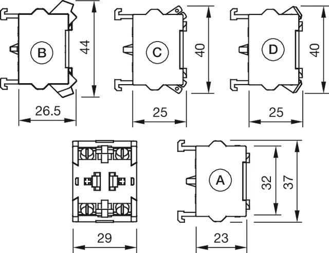 A = Screw terminal
B = Push-in terminal (PIT)
C = Plug-in terminal 6.3 mm x 0.8 mm
D = Double plug-in terminal 6.3 mm x 0.8 mm