Assembly settings
Mounting
Design
Flush
Flush
choose ...
Mounting type
Panel mounting
Panel mounting
choose ...
Operating-/Indication part
Lens illumination
Illuminated
Illuminated
choose ...
Electrical characteristics
Contacts
1 NC / 1 NO
1 NC / 1 NO
choose ...
Switching rating
250 V @ 5 A
250 V @ 5 A
choose ...
Mechanical Characteristics
Terminal
Plug-in terminal, 2.8 x 0.5 mm
Plug-in terminal, 2.8 x 0.5 mm
choose ...
Switching system
Snap-action switching element
Snap-action switching element
choose ...
Contact material
Gold
Gold
choose ...
Switching action
Momentary
Momentary
choose ...
Ambient Condition
IP front protection
IP65, according to DIN EN 60529
IP65, according to DIN EN 60529
choose ...
Back

Your product:

Mounting
- Design:
- Flush
- Mounting type:
- Panel mounting
Operating-/Indication part
- Lens illumination:
- Illuminated
Electrical characteristics
- Switching voltage and switching current:
250 VAC, 5 A (ohmic)
250 VAC, 3 A (Soldering terminal)
250 VAC, 2 A (inductive, cos(phi) = 0.7)
125 VAC, 3 A (inductive, cos(phi) = 0.7)
220 VDC, 0.1 A (inductive, L:R = 30 ms)
110 VDC, 0.2 A (inductive, L:R = 30 ms)
60 VDC, 0.7 A (inductive, L:R = 30 ms)
24 VDC, 2 A (inductive, L:R = 30 ms)
- Contacts:
- 1 NC / 1 NO
- Rated Operational Voltage Ue:
- 250 VAC/DC according to EN IEC 60947-1
- Switching rating:
- 250 V @ 5 A
- Electrical lifetime:
- 50 000 cycles of operation
- Electric strength:
- 2500 VAC, 50 Hz, 1 min. between all terminals and earth, according to IEC 61058-1, part 15
- Protection class:
- ll
- Standards:
- According to EN/IEC 61058-1
- Thermal current Ith:
- 5 A, according to EN / IEC 60947-5-1The maximum current in continuous operation and at ambient temperature not exceeding the quoted maximum values.
Mechanical Characteristics
- Terminal:
- Plug-in terminal, 2.8 x 0.5 mm
- Contact material:
- Gold
- Switching action:
- Momentary
- Switching system:
- Snap-action switching element
- Switching system:
- Self-cleaning, double-break snap action switching system, 1 normally closed and 1 normally open contact per element.
- Mechanical lifetime:
- 2 Mil. cycles of operation
- Operating force:
- 1,8 … 6 N, depending on the number of switching elements
- Operating Travel:
- 3 mm
- Tightening torque:
- Fixing nut max. 0.5 Nm
- Wire cross section:
- Snap-action switching element with axial soldering terminals, which can also be used as plug-in terminals 2.8 x 0.5mmMax. wire diameter 2 wires of 1 mmMax. wire cross-section of stranded cable 2 of 0.75 mm² or 1 x 1.0 mm²
- Weight:
- 0.007 kg
Ambient Condition
- IP front protection:
- IP65, according to DIN EN 60529
- Operating temperature:
- – 25 °C … + 55 °C, mounted as a block, make sure the heat can escape freely
- Storage temperature:
- – 40 °C … + 85 °C
- Shock resistance:
- 15 g for 11 ms, as per DIN / EN 60512-4-3, DIN / EN 60068-2-27 (Single impacts, semi-sinusoidal)
- Vibration resistance:
- 10 g at 10 Hz…1500 Hz, amplitude 0.75 mm (Sinusoidal), according to DIN EN 60512-4-4, DIN EN 60068-2-6
- Climate resistance:
- Standard condition, as per DIN EN 60068-2-30Changing condition, as per DIN EN 60068-2-14
Certificate
- Approbations:
- CB (IEC 61058-1), CQC, CSA, DNV, ENEC (EN 61058-1), UL
- Conformities:
- CE, UKCA, 2011 / 65 / EC (RoHS), 2014 / 30 / EU (EMC), 2014 / 35 / EU (LVD)
- REACH:
- REACH compliant
- RoHS:
- RoHS compliant
Other
- Short Description:
- Actuator, Illuminated, 1 NC / 1 NO, Momentary, Plug-in terminal, 2.8 x 0.5 mm, IP65, according to DIN EN 60529
- Housing colour:
- Black
- max. number of switching elements:
- 1
- Wiring diagrams:
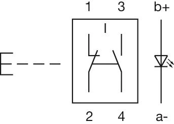
- Component layouts:
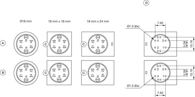 A = Universal terminal (rear side)
B = Plug-in terminal (rear side)
C = Anti twist device
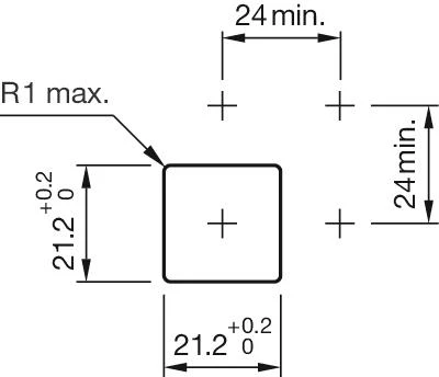
D = Drilling plan- Mounting cut-outs:
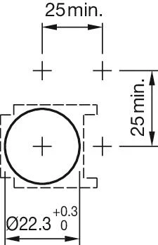
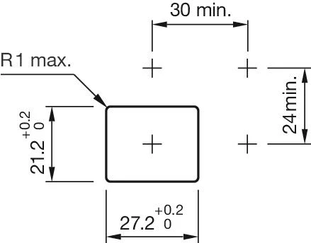
- Dimension drawings:
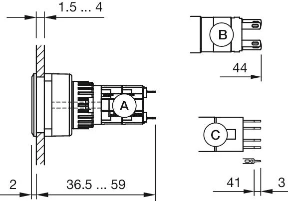 A = Solder terminal
B = Plug-in terminal 2.8 mm x 0.5 mm
C = Universal terminal 2.0 mm x 0.5 mm
Download files
Add to Cart