
Your product:

Mechanical Characteristics
- Terminal:
- PCB terminal
- Weight:
- 0.005 kg
Other
- Short Description:
- PCB plug-in base, PCB terminal, Axial
- Titel Accessory:
- PCB plug-in base
- Product attributes:
- For snap-action switching element, indicator- and diode element
- Pins:
- Axial
- Component layouts:
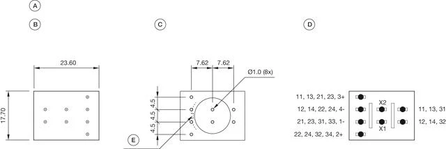 A = PCB plug-in base
B = Terminals (rear side)
C = Drilling plan (component side)
D = Occupancy plan (component side)
E = Anti-rotation device- Dimension drawings:
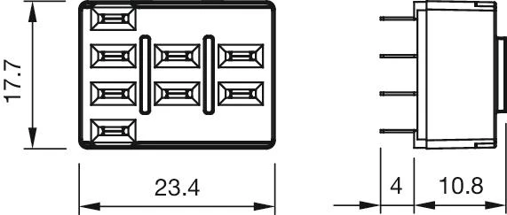 For Part No. 61-9821.1
Download files
Add to Cart