no
Round
Ø 37 mm
Raised
Panel mounting
Ø 22 mm
Mushroom-head
Red
Plastic
Non illuminated
1 FS + 1 NC + 1 NO
500 V AC @ 6 A
Twist to unlock
Double plug-in terminal, 6.3 x 0.8 mm
Slow-make switching element
Silver
Maintained
IP65
Arrows
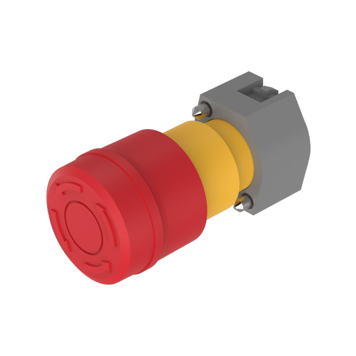
Emergency stop switch, Series 04, Ø 37 mm, Raised, 1 FS + 1 NC + 1 NO, IP65, Double plug-in terminal, 6.3 x 0.8 mm
- 704.064.2A
- 704.915.1/D-1
- 704.915.4/DFS-1
- Release type
- Contact material
- Switching rating
- Terminal
- Contacts configuration

- Contact material
- Terminal
- Contacts configuration

- HMI function:
- Emergency stop switch
- Series:
- Series 04
- Front dimension:
- Ø 37 mm
- Front form:
- Round
- Design:
- Raised
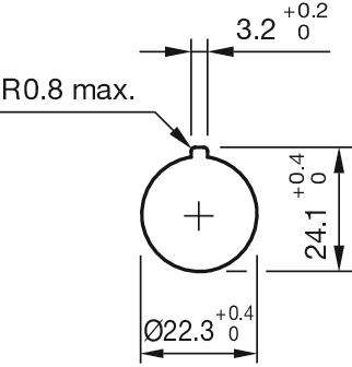
- Mounting cut-out:
- Ø 22.5 mm
- Mounting type:
- Panel mounting
- Lens colour:
- Red
- Lens material:
- Plastic
- Lens illumination:
- Non illuminated
- Lens shape:
- Mushroom-head
- Lens optics:
- opaque
- Switching voltage and switching current:
as per DIN EN IEC 60947-5-1
voltage
DC13
AC15
24 V
4.0 A
8.0 A
60 V
1.5 A
8.0 A
110 V
1.0 A
120 V
8.0 A
230 V
0.4 A
7.0 A
400 V
0.2 A
5.0 A
500 V
0.15 A
4.0 A
as per UL 60947-5-1
voltage
power
24 VDC
4.0 A, Pilot duty
60 VDC
1.5 A, Pilot duty
120 VDC
1.0 A, Pilot duty
240 VDC
0.4 A, Pilot duty
415 VDC
0.2 A, Pilot duty
480 VDC
0.14A, Pilot duty
120 VAC
8.0 A, Pilot duty
240 VAC
7.0 A, Pilot duty
415 VAC
5.0 A, Pilot duty
480 VAC
4.0 A, Pilot duty
For voltages greater than Ue = 400 V,
the grid dimensions must not be
less than 35 mm x 50 mm.
- Contacts configuration:
- 1 FS + 1 NC + 1 NO
- Switching rating:
- 500 V AC @ 6 A
- Electrical lifetime:
- 50 000 cycles of operation (500 VAC, 10 A)
- Thermal current Ith:
- Max. current as per EN IEC 60947-5-1 10 A
- Terminal:
- Double plug-in terminal, 6.3 x 0.8 mm
- Contact material:
- Silver
- Switching action:
- Maintained
- Switching system:
- Slow-make switching element
- Release type:
- Twist to unlock
- Total weight:
- 0.09 kg
- IP front protection:
- IP65
- Operating temperature:
- – 25 °C … + 55 °C
- Vibration resistance:
- (sinusförmig) 100 m/s² bei 10 Hz…500 Hz, nach DIN EN 60068-2-6, Erhöhtes Breitbandrauschen nach DIN EN 61373, Klasse 1B
- Approbations:
- UL, CE, CCC, EN 60947-5-5, ISO 13850
- Housing colour:
- Yellow
- Housing material:
- Plastic
- Marking:
- Arrows
- Product attributes:
- Twist to unlock anti-clockwise
- max. number of switching elements:
- 2
- Assembly instruction video:
- https://vimeo.com/eaohmi/assembly-instruction-e-stop-s04
- Wiring diagrams:

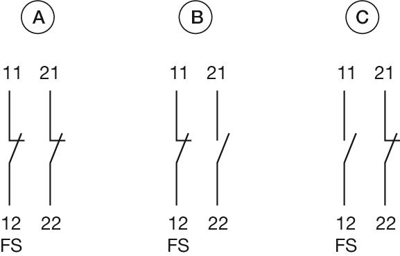 A = mounted, not actuated
B = mounted, actuated
C = not mounted, not actuated

- Front dimension:
- Ø 37 mm
- Front form:
- Round
- Design:
- Raised
- Mounting type:
- Panel mounting
- Lens colour:
- Red
- Lens material:
- Plastic
- Lens illumination:
- Non illuminated
- Lens shape:
- Mushroom-head
- Lens optics:
- opaque
- Switching action:
- Maintained
- Release type:
- Twist to unlock
- Mechanical lifetime:
- ≥50 000 cycles of operation
- Operating force:
- 8 N
- Operating Travel:
- ca. 5.8 mm ± 0.2 mm
- Weight:
- 0.048 kg
- IP Protection:
- IP65 front side
- Operating temperature:
- – 25 °C … + 55 °C
- Storage temperature:
- – 40 °C … + 85 °C
- REACH:
- REACH compliant
- RoHS:
- RoHS compliant
- Short Description:
- Actuator, Ø 37 mm, Mushroom-head, Non illuminated, Red, Plastic, opaque, Round, Maintained, Twist to unlock
- Housing colour:
- Yellow
- Housing material:
- Plastic
- Marking:
- Arrows
- Product attributes:
- Twist to unlock anti-clockwise
- Hints:
- Shaft yellow
- Wiring diagrams:
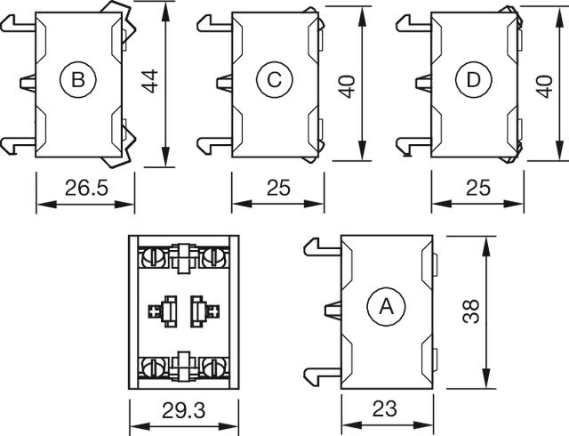
- Mounting cut-outs:
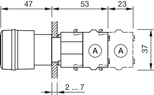
- Dimension drawings:
 A = Screw terminal

- Switching voltage and switching current:
as per DIN EN IEC 60947-5-1
voltage
DC13
AC15
24 V
4.0 A
8.0 A
60 V
1.5 A
8.0 A
110 V
1.0 A
120 V
8.0 A
230 V
0.4 A
7.0 A
400 V
0.2 A
5.0 A
500 V
0.15 A
4.0 A
as per UL 60947-5-1
voltage
power
24 VDC
4.0 A, Pilot duty
60 VDC
1.5 A, Pilot duty
120 VDC
1.0 A, Pilot duty
240 VDC
0.4 A, Pilot duty
415 VDC
0.2 A, Pilot duty
480 VDC
0.14A, Pilot duty
120 VAC
8.0 A, Pilot duty
240 VAC
7.0 A, Pilot duty
415 VAC
5.0 A, Pilot duty
480 VAC
4.0 A, Pilot duty
For voltages greater than Ue = 400 V,
the grid dimensions must not be
less than 35 mm x 50 mm.
- Contacts:
- 1 NO
- Rated impulse withstand voltage Uimp:
- 4 kV
- Rated insulation voltage Ui:
- 500 V
- Recommended minimum operational data:
Gold-silver contacts
Voltage
24 VDC
110 VDC
Current
5 mA
2 mA
Hard silver contacts
Voltage
24 VDC
110 VDC
Current
50 mA
10 mA
- Switching rating:
- 500 V AC @ 6 A
- Electrical lifetime:
- 50 000 cycles of operation (500 VAC, 10 A)
- Pollution degree:
- 3
- Standards:
- The switches comply with the “Standards for low-voltage switching devices” DIN EN IEC UL 60947-5-1
- Thermal current Ith:
- Max. current as per EN IEC 60947-5-1 10 A
- Terminal:
- Double plug-in terminal, 6.3 x 0.8 mm
- Contact material:
- Silver
- Switching system:
- Slow-make switching element
- Switching system:
- The double-break, slow-make switching element is equipped with one or two independent contact systems, acting as normally open or normally closed contact. The normally closed contact has forced opening.Slow-make contacts with forced action are ideal for high switch ratings.
- Operating force:
- 1 Normally closed approx. 2 N, 1 Normally open approx. 3 N
- Wire cross section:
- Double plug-in terminal 2 x 6.3 mm x 0.8 mmFor switches with plug-in terminals it is necessary to provide insulation sleeves and to maintain a spacing of 65 mm between rows (mounting cut-outs).
- Weight:
- 0.018 kg
- IP Protection:
- IP00
- Operating temperature:
- – 40 °C … + 55 °C
- Storage temperature:
- – 40 °C … + 85 °C
- Shock resistance:
- (single impacts, semi-sinusoidal) 300 m/s², pulse width 18 ms, as per DIN EN 60068-2-27
- Vibration resistance:
- (sinusförmig) 100 m/s² bei 10 Hz…500 Hz, nach DIN EN 60068-2-6, Erhöhtes Breitbandrauschen nach DIN EN 61373, Klasse 1B
- Climate resistance:
- Relative humidity 10 %rh ... 95 %rh (non-condensing) original packaging according to DIN EN IEC 60721-3-1 Class 1C1
- Approbations:
- CB (IEC 60947-5-1), cULus, DNV, VDE
- Conformities:
- CE, CCC, UKCA
- REACH:
- REACH compliant
- RoHS:
- RoHS compliant
- Short Description:
- Switching element - New Version, Slow-make switching element, 500 V AC @ 6 A, Silver, 1 NO, Double plug-in terminal, 6.3 x 0.8 mm
- Hints:
- When using the switching element, the application guidelines must be observed.For the third switching element the terminal marking insert is to be ordered separatelyOperating temperature: Other temperatures on requestA suitable enclosure is required for applications with increased protection requirements. In North America, the product must be installed in an enclosure in accordance with UL 50E Type 2 or higher.
- Special requirements:
Special requirements for positive-opening auxiliary current switches
Positive opening travel
Emergency stop 12.5 mm
Minimum force
Emergency stop 50 N (actuating force at
which is safely switched)
Max. travel
Emergency stop 12.5 mm
- Wiring diagrams:
- Dimension drawings:


- Switching voltage and switching current:
as per DIN EN IEC 60947-5-1
voltage
DC13
AC15
24 V
4.0 A
8.0 A
60 V
1.5 A
8.0 A
110 V
1.0 A
120 V
8.0 A
230 V
0.4 A
7.0 A
400 V
0.2 A
5.0 A
500 V
0.15 A
4.0 A
as per UL 60947-5-1
voltage
power
24 VDC
4.0 A, Pilot duty
60 VDC
1.5 A, Pilot duty
120 VDC
1.0 A, Pilot duty
240 VDC
0.4 A, Pilot duty
415 VDC
0.2 A, Pilot duty
480 VDC
0.14A, Pilot duty
120 VAC
8.0 A, Pilot duty
240 VAC
7.0 A, Pilot duty
415 VAC
5.0 A, Pilot duty
480 VAC
4.0 A, Pilot duty
For voltages greater than Ue = 400 V,
the grid dimensions must not be
less than 35 mm x 50 mm.
- Contacts:
- 1 NC / 1 FS
- Rated impulse withstand voltage Uimp:
- 4 kV
- Rated insulation voltage Ui:
- 500 V
- Recommended minimum operational data:
Gold-silver contacts
Voltage
24 VDC
110 VDC
Current
5 mA
2 mA
Hard silver contacts
Voltage
24 VDC
110 VDC
Current
50 mA
10 mA
- Switching rating:
- 500 V @ 10 A
- Electrical lifetime:
- 50 000 cycles of operation (500 VAC, 10 A)
- Pollution degree:
- 3
- Standards:
- The switches comply with the “Standards for low-voltage switching devices” DIN EN IEC UL 60947-5-1
- Thermal current Ith:
- Max. current as per EN IEC 60947-5-1 10 A
- Terminal:
- Double plug-in terminal, 6.3 x 0.8 mm
- Contact material:
- Silver
- Switching system:
- Slow-make switching element
- Switching system:
- The double-break, slow-make switching element is equipped with one or two independent contact systems, acting as normally open or normally closed contact. The normally closed contact has forced opening.Slow-make contacts with forced action are ideal for high switch ratings.
- Operating force:
- 1 Normally closed approx. 2 N, 1 Normally open approx. 3 N
- Wire cross section:
- Double plug-in terminal 2 x 6.3 mm x 0.8 mm
- Weight:
- 0.024 kg
- IP Protection:
- IP00
- Operating temperature:
- – 40 °C … + 55 °C
- Storage temperature:
- – 40 °C … + 85 °C
- Shock resistance:
- (single impacts, semi-sinusoidal) 300 m/s², pulse width 18 ms, as per DIN EN 60068-2-27
- Vibration resistance:
- (sinusförmig) 100 m/s² bei 10 Hz…500 Hz, nach DIN EN 60068-2-6, Erhöhtes Breitbandrauschen nach DIN EN 61373, Klasse 1B
- Climate resistance:
- Relative humidity 10 %rh ... 95 %rh (non-condensing) original packaging according to DIN EN IEC 60721-3-1 Class 1C1
- Approbations:
- CB (IEC 60947-5-1), cULus, DNV, VDE
- Conformities:
- CE, CCC, UKCA
- REACH:
- REACH compliant
- RoHS:
- RoHS compliant
- Short Description:
- Switching element - New Version, Slow-make switching element, 500 V @ 10 A, Silver, 1 NC / 1 FS, Double plug-in terminal, 6.3 x 0.8 mm
- Hints:
- When using the switching element, the application guidelines must be observed.For the third switching element the terminal marking insert is to be ordered separatelyOperating temperature: Other temperatures on requestA suitable enclosure is required for applications with increased protection requirements. In North America, the product must be installed in an enclosure in accordance with UL 50E Type 2 or higher.
- Special requirements:
Special requirements for positive-opening auxiliary current switches
Positive opening travel
Emergency stop 12.5 mm
Minimum force
Emergency stop 50 N (actuating force at
which is safely switched)
Max. travel
Emergency stop 12.5 mm
- Wiring diagrams:
- A = mounted, not actuated
B = mounted, actuated
C = not mounted, not actuated - Dimension drawings: