Assembly settings
Assortiment
Online beschikbaarheid
Ja
yes
kiezen...
Voor
Front form
Rectangular
Rectangular
kiezen...
Front bezel colour
Black
Black
kiezen...
Front bezel material
Plastic
Plastic
kiezen...
Front dimension
24 mm x 18 mm
24 mm x 18 mm
kiezen...
Montage
Design
Raised
Raised
kiezen...
Mounting type
Panel mounting
Panel mounting
kiezen...
Mounting cut-out
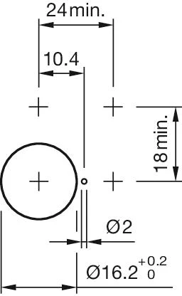
Ø 16 mm
Ø 16 mm
kiezen...
Mechanische kenmerken
Terminal
Plug-in terminal, 2.8 x 0.5 mm
Plug-in terminal, 2.8 x 0.5 mm
kiezen...
Omgevingscondities
IP front protection
IP40
IP40
kiezen...
Terug
Buzzer, Series 51, 24 mm x 18 mm, Raised, Plug-in terminal, 2.8 x 0.5 mm
- 51-801.002
- Terminal

Accessoires & gereedschap toevoegen
Uw product:
Assortiment
- HMI function:
- Buzzer
- Series:
- Series 51
Voor
- Front dimension:
- 24 mm x 18 mm
- Front form:
- Rectangular
- Front bezel colour:
- Black
- Front bezel material:
- Plastic
Montage
- Design:
- Raised
- Mounting cut-out:
- Ø 16 mm
- Mounting type:
- Panel mounting
Mechanische kenmerken
- Terminal:
- Plug-in terminal, 2.8 x 0.5 mm
- Tightening torque:
- Fixing nut max. 0.5 Nm
- Totaal gewicht:
- 0.009 kg
Akoestische eigenschappen
- Tone frequency:
- 2.1 kHz
- Sound pressure:
- 88dB (A) ±8dB at a distance of 0.1m
Omgevingscondities
- IP front protection:
- IP40
- Operating temperature:
- – 25 °C … + 55 °C
Meer
- Housing colour:
- Black
- Housing material:
- Plastic
- Product attributes:
- Further information see Technical data
- Wiring diagrams:
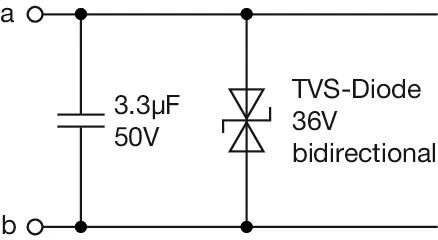 Recommended Protection Circuit: If the buzzer is not indirectly protected against surge impulses by an EMC-compliant power supply or if the cable length exceeds 30 m, additional protection measures are recommended. In this case, a bidirectional TVS diode should be installed between the connection wires as close to the buzzer as possible, as shown in the schematic above. To suppress conducted emissions, a ceramic capacitor of 3.3 µF / 50 V should additionally be connected at the buzzer terminals [a] and [b].
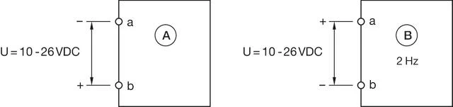 A = Continuous tone
B = Interval tone 2Hz
Product opslaan of delen
Bestanden downloaden
Toevoegen aan winkelwagentje
Uw product bestaat uit het volgende 1 COMPONENTS:

Voor
- Front dimension:
- 24 mm x 18 mm
- Front form:
- Rectangular
- Front bezel colour:
- Black
- Front bezel material:
- Plastic
Montage
- Design:
- Raised
- Mounting cut-out:
- Ø 16 mm
- Mounting type:
- Panel mounting
Elektrische kenmerken
- Operating Voltage and Current:
Typ. 10 VDC ... 26 VDC, ≤ 20mA
Mechanische kenmerken
- Terminal:
- Plug-in terminal, 2.8 x 0.5 mm
- Tightening torque:
- Fixing nut max. 0.5 Nm
- Weight:
- 0.009 kg
Akoestische eigenschappen
- Tone frequency:
- 2.1 kHz
- Sound pressure:
- 88dB (A) ±8dB at a distance of 0.1m
Omgevingscondities
- IP Protection:
- IP40
- Operating temperature:
- – 25 °C … + 55 °C
- Storage temperature:
- – 40 °C … + 85 °C
Certificaten
- Approbations:
- DNV
- Conformities:
- CE, UKCA, 2011 / 65 / EC (RoHS), 2014 / 35 / EU (LVD)
- REACH:
- REACH compliant
- RoHS:
- RoHS compliant
Meer
- Short Description:
- Actuator, Ø 16 mm, 24 mm x 18 mm, Rectangular, Black, Plastic, Plug-in terminal, 2.8 x 0.5 mm
- Housing colour:
- Black
- Housing material:
- Plastic
- Product attributes:
- Further information see Technical data
- Buzzer system:
- Electronic non-contacting buzzer with IC oscillator
- Wiring diagrams:
- Recommended Protection Circuit: If the buzzer is not indirectly protected against surge impulses by an EMC-compliant power supply or if the cable length exceeds 30 m, additional protection measures are recommended. In this case, a bidirectional TVS diode should be installed between the connection wires as close to the buzzer as possible, as shown in the schematic above. To suppress conducted emissions, a ceramic capacitor of 3.3 µF / 50 V should additionally be connected at the buzzer terminals [a] and [b].A = Continuous tone
B = Interval tone 2Hz - Mounting cut-outs:
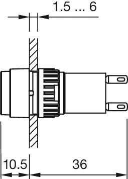
- Dimension drawings:
Bestanden downloaden
Waar te koop
Toevoegen aan winkelwagentje