Assembly settings
Anteriore
Front form
Square
Square
scegliere ...
Front dimension
18 mm x 18 mm
18 mm x 18 mm
scegliere ...
Montaggio
Design
Flush
Flush
scegliere ...
Mounting type
Panel mounting
Panel mounting
scegliere ...
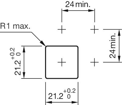
Mounting cut-out
21 mm x 21 mm
21 mm x 21 mm
scegliere ...
Caratteristiche elettriche
Contacts
2 NC / 2 NO
2 NC / 2 NO
scegliere ...
Switching rating
250 V @ 5 A
250 V @ 5 A
scegliere ...
Caratteristiche meccaniche
Terminal
Soldering terminal
Soldering terminal
scegliere ...
Switching positions
2 positions
2 positions
scegliere ...
Switching system
Snap-action switching element
Snap-action switching element
scegliere ...
Contact material
Gold
Gold
scegliere ...
Switching action
Rest (a) - Maintained (a)
Rest (a) - Maintained (a)
scegliere ...
Switching angle
90° right
90° right
scegliere ...
Condizioni ambientali
IP front protection
IP65, according to DIN EN 60529
IP65, according to DIN EN 60529
scegliere ...
Indietro

Il vostro prodotto:

Anteriore
- Front dimension:
- 18 mm x 18 mm
- Front form:
- Square
Montaggio
- Design:
- Flush
- Mounting cut-out:
- 21 mm x 21 mm
- Mounting type:
- Panel mounting
Caratteristiche elettriche
- Switching voltage and switching current:
250 VAC, 5 A (ohmic)
250 VAC, 3 A (Soldering terminal)
250 VAC, 2 A (inductive, cos(phi) = 0.7)
125 VAC, 3 A (inductive, cos(phi) = 0.7)
220 VDC, 0.1 A (inductive, L:R = 30 ms)
110 VDC, 0.2 A (inductive, L:R = 30 ms)
60 VDC, 0.7 A (inductive, L:R = 30 ms)
24 VDC, 2 A (inductive, L:R = 30 ms)
- Contacts:
- 2 NC / 2 NO
- Rated Operational Voltage Ue:
- 250 VAC/DC according to EN IEC 60947-1
- Switching rating:
- 250 V @ 5 A
- Electrical lifetime:
- 50 000 cycles of operation
- Electric strength:
- 2500 VAC, 50 Hz, 1 min. between all terminals and earth, according to IEC 61058-1, part 15
- Protection class:
- ll
- Standards:
- According to EN/IEC 61058-1
- Thermal current Ith:
- 5 A, according to EN / IEC 60947-5-1The maximum current in continuous operation and at ambient temperature not exceeding the quoted maximum values.
Caratteristiche meccaniche
- Terminal:
- Soldering terminal
- Contact material:
- Gold
- Switching action:
- Rest (a) - Maintained (a)
- Switching system:
- Snap-action switching element
- Switching system:
- Self-cleaning, double-break snap action switching system, 1 normally closed and 1 normally open contact per element.
- Switching positions:
- 2 positions
- Switching angle:
- 90° right
- Mechanical lifetime:
- 50 000 cycles of operation
- Operating force:
- 1,8 … 6 N, depending on the number of switching elements
- Tightening torque:
- Fixing nut max. 0.5 Nm
- Wire cross section:
- Snap-action switching element with tinned soldering terminals at the sidesMax. wire diameter 2 wires à 1.2 mmMax. wire cross-section of stranded cable 1 x 1 mm²
- Weight:
- 0.018 kg
Condizioni ambientali
- IP front protection:
- IP65, according to DIN EN 60529
- Operating temperature:
- – 25 °C … + 55 °C
- Storage temperature:
- – 40 °C … + 85 °C
- Shock resistance:
- 15 g for 11 ms, as per DIN / EN 60512-4-3, DIN / EN 60068-2-27 (Single impacts, semi-sinusoidal)
- Vibration resistance:
- 10 g at 10 Hz…1500 Hz, amplitude 0.75 mm (Sinusoidal), according to DIN EN 60512-4-4, DIN EN 60068-2-6
- Climate resistance:
- Standard condition, as per DIN EN 60068-2-30Changing condition, as per DIN EN 60068-2-14
Certificati
- Approbations:
- CB (IEC 61058-1), CQC, CSA, DNV, ENEC (EN 61058-1), UL
- Conformities:
- CE, UKCA, 2011 / 65 / EC (RoHS), 2014 / 30 / EU (EMC), 2014 / 35 / EU (LVD)
- REACH:
- REACH compliant
- RoHS:
- RoHS compliant
Di più
- Short Description:
- Actuator, 21 mm x 21 mm, 18 mm x 18 mm, Square, 2 NC / 2 NO, Rest (a) - Maintained (a), Soldering terminal, IP65, according to DIN EN 60529
- Housing colour:
- Black
- Hints:
- Standard lock: DOM 311
- max. number of switching elements:
- 4
- Switching positions:
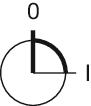
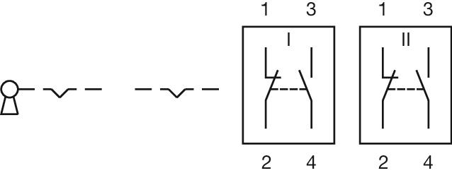
- Wiring diagrams:
- Mounting cut-outs:
- Dimension drawings:
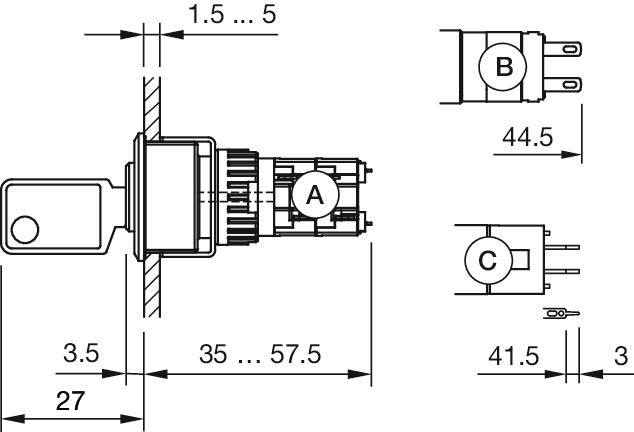 A = Solder terminal
B = Solder terminal 2.8 mm x 0.5 mm
C = Universal terminal 2.0 mm x 0.5 mm
Scarica i file
Aggiungi al carrello