Assembly settings
Front
Front form
Round
Round
choisir ...
Front bezel colour
Nature
Nature
choisir ...
Front bezel material
Aluminium
Aluminium
choisir ...
Montage
Mounting type
Panel mounting
Panel mounting
choisir ...
Partie commande/affichage
Lever shape
short
short
choisir ...
Lever colour
Black
Black
choisir ...
Caractéristiques électriques
Contacts
2 NO
2 NO
choisir ...
Switching rating
42 V @ 0,1 A
42 V @ 0,1 A
choisir ...
Caractéristiques mécaniques
Terminal
Universal terminal, 2 x 0.5 mm
Universal terminal, 2 x 0.5 mm
choisir ...
Switching positions
2 positions
2 positions
choisir ...
Switching system
Low-level element
Low-level element
choisir ...
Contact material
Gold
Gold
choisir ...
Switching action
Rest - Momentary
Rest - Momentary
choisir ...
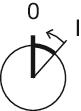
Switching angle
42° right
42° right
choisir ...
Conditions environnementales
IP front protection
IP67, according to DIN EN 60529
IP67, according to DIN EN 60529
choisir ...
Retour

Votre produit:

Front
- Front form:
- Round
- Front bezel colour:
- Nature
- Front bezel material:
- Aluminium
Montage
- Mounting type:
- Panel mounting
Partie commande/affichage
- Lever colour:
- Black
- Lever material:
- plastic
- Lever shape:
- short
Caractéristiques électriques
- Switching voltage and switching current:
- 100 mA at 42 VAC/VDC
- Contacts:
- 2 NO
- Switching rating:
- 42 V @ 0,1 A
- Electric strength:
- 3000 VAC, 50 Hz, 1 min. between all terminals and earth, according to EN/IEC 61058-1
- Protection class:
- ll
Caractéristiques mécaniques
- Terminal:
- Universal terminal, 2 x 0.5 mm
- Contact material:
- Gold
- Switching action:
- Rest - Momentary
- Switching system:
- Low-level element
- Switching system:
- This low-level switching element was designed for switching low powers in electronic circuits. The mechanism assures reliable switching of loads ranging from a few μA/μV up to 100 mA/ 42 VAC/DC.Single-break momentary contact, as normally open or normally closed with 4 independent points of contact. 2 momentary contactsper switching element; combination of normally open and normally closed is possible.Special features are the long life, extremely short rebound time and stable contact resistance.
- Switching positions:
- 2 positions
- Switching angle:
- 42° right
- Mechanical lifetime:
- 5 Mil. cycles of operation
- Operating force:
- 3 N … 4 N, depending on the number of switching elements
- Tightening torque:
- Fixing nut max. 0.25 Nm
- Terminal details 1:
- The universal terminals permit these units to be mounted on printed circuit boards (PCB). These terminals can also be used as soldering or plug-in terminals.For these terminals we can also supply a plug-in base which, when soldered on to the board, enables the switch to be plugged in.
- Wire cross section:
- Max. wire diameter 2 wires of 1 mmMax. wire cross-section of stranded cable 2 x 0.75 mm²
- Weight:
- 0.025 kg
Conditions environnementales
- IP front protection:
- IP67, according to DIN EN 60529
- Operating temperature:
- – 25 °C … + 55 °C, mounted as a block, make sure the heat can escape freely
- Storage temperature:
- – 40 °C … + 85 °C
- Shock resistance:
- Max. 150 m / s², pulse width 11 ms, 3-axis, (semi-sinusoidal as per EN IEC 60068-2-27)
Certificats
- Conformities:
- 2011 / 65 / EC (RoHS), 2014 / 35 / EU (LVD)
- REACH:
- REACH compliant
- RoHS:
- RoHS compliant
Autres
- Short Description:
- Actuator, non illuminative, Black, short, Round, Nature, Aluminium, anodised, 2 NO, Rest - Momentary, Universal terminal, 2 x 0.5 mm, IP67, according to DIN EN 60529
- Hints:
- The colour of anodised aluminium parts can vary due to technical production reasons
- Switching positions:
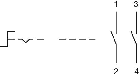
- Wiring diagrams:
- Component layouts:
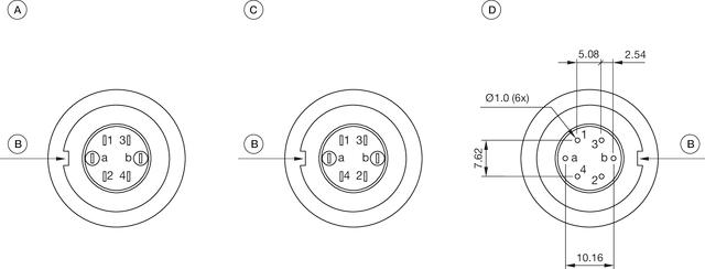 A = Terminals (rear side)
B = Anti twist device
C = Diode block
D = Drilling plan (component side)- Mounting cut-outs:
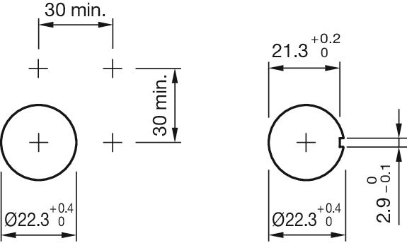
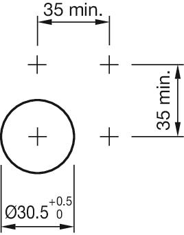
- Dimension drawings:
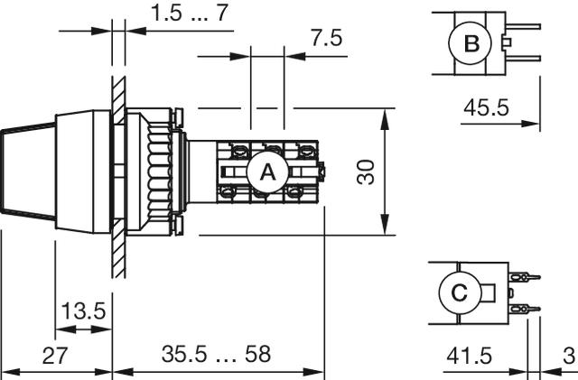 A = Solder terminal
B = Plug-in terminal 2.8 x 0.5 mm
C = Universal terminal 2.0 mm x 0.5 mm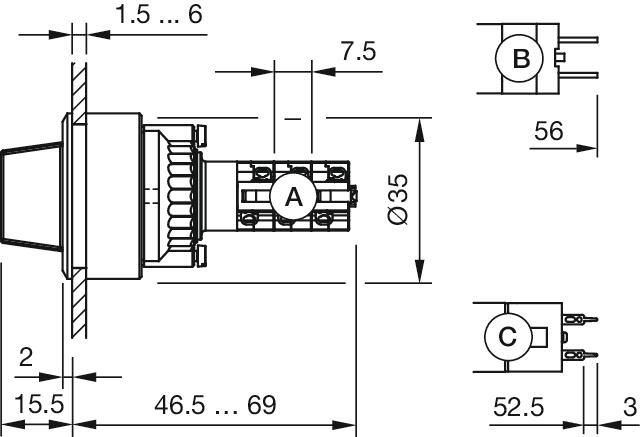 A = Solder terminal
B = Plug-in terminal 2.8 x 0.5 mm
C = Universal terminal 2.0 mm x 0.5 mm
Télécharger des fichiers
Ajouter au panier