Assembly settings
제품 라인업
즉시 이용 가능
아니
no
선택하다 ...
정면
Front form
Round
Round
선택하다 ...
Front bezel colour
Nature
Nature
선택하다 ...
Front bezel material
Aluminium
Aluminium
선택하다 ...
Front dimension
Ø 25 mm
Ø 25 mm
선택하다 ...
장착
Design
Flush
Flush
선택하다 ...
Mounting type
Panel mounting
Panel mounting
선택하다 ...
Mounting cut-out
Ø 22 mm
Ø 22 mm
선택하다 ...
작동/표시 부분
Lens shape
Flush
Flush
선택하다 ...
Lens colour
Colourless
Colourless
선택하다 ...
Lens material
Plastic, according to UL 94 HB
Plastic, according to UL 94 HB
선택하다 ...
Lens illumination
Illuminated
Illuminated
선택하다 ...
Shape of illumination
Front
Front
선택하다 ...
Illumination colour
Red
Red
선택하다 ...
전기적 특성
연락처 설정
2 NO
2 NO
선택하다 ...
Switching rating
42 V @ 0,1 A
42 V @ 0,1 A
선택하다 ...
Operating voltage kind of
V AC/DC
V AC/DC
선택하다 ...
Operating voltage
12 V
12 V
선택하다 ...
기계적 특성
Terminal
Universal terminal, 2 x 0.5 mm
Universal terminal, 2 x 0.5 mm
선택하다 ...
Switching system
Low-level element
Low-level element
선택하다 ...
Contact material
Gold
Gold
선택하다 ...
Switching action
Momentary
Momentary
선택하다 ...
주변 환경
IP front protection
IP65
IP65
선택하다 ...
뒤로
Illuminated push button, Series 51, Ø 25 mm, illuminative, Flush, 2 NO, Gold, IP65, Universal terminal, 2 x 0.5 mm
- 61-9642.7
- 51-451.036F
- 61-9933.0
- 10-2J09.1062
- Lens colour
- Lens material
- Shape of illumination

- Switching system
- Terminal
- Switching action
- Switching rating
- 연락처 설정

- Front bezel colour
- Front bezel material

- Operating voltage kind of
- Illumination colour
- Operating voltage

액세서리 및 도구 추가
귀사의 제품:
제품 라인업
- HMI function:
- Illuminated push button
- 시리즈:
- Series 51
정면
- Front dimension:
- Ø 25 mm
- Front form:
- Round
- Front bezel colour:
- Nature
- Front bezel material:
- Aluminium
장착
- Design:
- Flush
- Mounting cut-out:
- Ø 22.5 mm
- Mounting type:
- Panel mounting
작동/표시 부분
- Lens colour:
- Colourless
- Lens material:
- Plastic, according to UL 94 HB
- Lens illumination:
- Illuminated
- Lens shape:
- Flush
- Lens optics:
- transparent
- Illumination colour:
- Red
- Shape of illumination:
- Front
전기적 특성
- Switching voltage and switching current:
- 100 mA at 42 VAC/VDC
- 연락처 설정:
- 2 NO
- Operating voltage:
- 12 V AC/DC +10%
- Operation current:
- 7 - 14 mA ±15 %
- Switching rating:
- 42 V @ 0,1 A
- Lumi. Intensity:
- 330 mcd
기계적 특성
- Terminal:
- Universal terminal, 2 x 0.5 mm
- Contact material:
- Gold
- Switching action:
- Momentary
- Switching system:
- Low-level element
- Tightening torque:
- Fixing nut max. 0.5 Nm
- 총 중량:
- 0.014 kg
주변 환경
- IP front protection:
- IP65
- Operating temperature:
- – 25 °C … + 55 °C, mounted as a block, make sure the heat can escape freely
기타
- Housing colour:
- Black
- Product attributes:
- For indicator, push button, illuminated push button
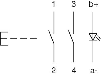
- Wiring diagrams:

이 제품을 공유하고 저장하세요
파일 다운로드
장바구니에 담기
귀사의 제품은 다음과 같이 구성됩니다 4 COMPONENTS:

정면
- Front form:
- Round
작동/표시 부분
- Lens colour:
- Colourless
- Lens material:
- Plastic, according to UL 94 HB
- Lens illumination:
- Illuminated
- Lens shape:
- Flush
- Lens optics:
- transparent
- Shape of illumination:
- Front
기계적 특성
- Weight:
- 0.001 kg
증명서
- REACH:
- REACH compliant
- RoHS:
- RoHS compliant
기타
- Short Description:
- Lens, Ø 19.7 mm, Illuminated, Colourless, Flush, Plastic, according to UL 94 HB
- Dimension:
- Ø 19.7 mm
파일 다운로드
어디서 구입할 수 있나요?
장바구니에 담기

장착
- Design:
- Flush
- Mounting type:
- Panel mounting
작동/표시 부분
- Lens illumination:
- Illuminated
전기적 특성
- Switching voltage and switching current:
- 100 mA at 42 VAC/VDC
- Contacts:
- 2 NO
- Switching rating:
- 42 V @ 0,1 A
- Electric strength:
- 2500 VAC, 50 Hz, 1 min. between all terminals and earth, according to IEC 61058-1, part 15
기계적 특성
- Terminal:
- Universal terminal, 2 x 0.5 mm
- Contact material:
- Gold
- Switching action:
- Momentary
- Switching system:
- Low-level element
- Switching system:
- This low-level switching element was designed for switching low powers in electronic circuits. The mechanism assures reliable switching of loads ranging from a few μA/μV up to 100 mA/ 42 VAC/DC.Single-break momentary contact, as normally open or normally closed with 4 independent points of contact. 2 momentary contactsper switching element; combination of normally open and normally closed is possible.Special features are the long life, extremely short rebound time and stable contact resistance.
- Mechanical lifetime:
- 5 Mil. cycles of operation
- Operating force:
- 1,8 … 3,5 N
- Operating Travel:
- 3 mm
- Tightening torque:
- Fixing nut max. 0.5 Nm
- Terminal details 1:
- The universal terminals permit these units to be mounted on printed circuit boards (PCB). These terminals can also be used as soldering or plug-in terminals.For these terminals we can also supply a plug-in base which, when soldered on to the board, enables the switch to be plugged in.
- Weight:
- 0.007 kg
주변 환경
- IP front protection:
- IP65, according to DIN EN 60529
- Operating temperature:
- – 25 °C … + 55 °C, mounted as a block, make sure the heat can escape freely
- Storage temperature:
- – 40 °C … + 85 °C
- Shock resistance:
- 15 g for 11 ms, as per DIN / EN 60512-4-3, DIN / EN 60068-2-27 (Single impacts, semi-sinusoidal)
증명서
- REACH:
- REACH compliant
- RoHS:
- RoHS compliant
기타
- Short Description:
- Actuator, Illuminated, 2 NO, Momentary, Universal terminal, 2 x 0.5 mm, IP65, according to DIN EN 60529
- Housing colour:
- Black
- Wiring diagrams:
- Component layouts:
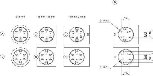 A = Universal terminal (rear side)
B = Plug-in terminal (rear side)
C = Anti twist device
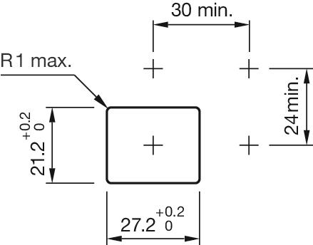
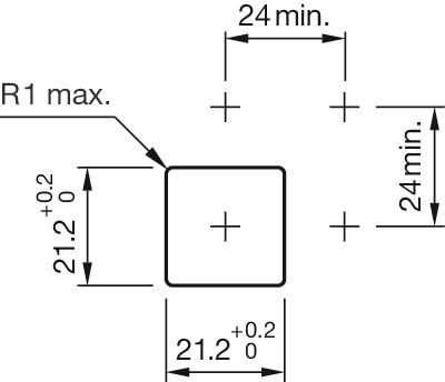
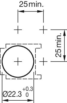
D = Drilling plan- Mounting cut-outs:

- Dimension drawings:
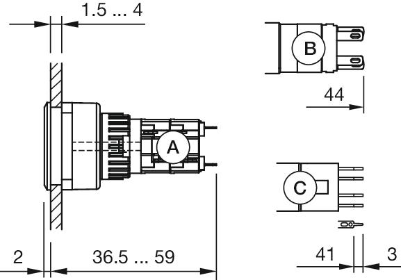 A = Solder terminal
B = Plug-in terminal 2.8 mm x 0.5 mm
C = Universal terminal 2.0 mm x 0.5 mm
파일 다운로드
어디서 구입할 수 있나요?
장바구니에 담기

정면
- Front dimension:
- Ø 25 mm
- Front form:
- Round
- Front bezel colour:
- Nature
- Front bezel material:
- Aluminium
장착
- Mounting cut-out:
- Ø 22.5 mm
- Mounting type:
- Panel mounting
기계적 특성
- Weight:
- 0.005 kg
증명서
- REACH:
- REACH compliant
- RoHS:
- RoHS compliant
기타
- Short Description:
- Front bezel set, Ø 25 mm, Ø 19,7 mm, Nature, Aluminium
- Dimension:
- Ø 25 mm
- Internal size:
- Ø 19,7 mm
- Product attributes:
- For indicator, push button, illuminated push button
- Hints:
- The colour of anodised aluminium parts can vary due to technical production reasons
- Mounting cut-outs:
파일 다운로드
어디서 구입할 수 있나요?
장바구니에 담기

작동/표시 부분
- Illumination colour:
- Red
전기적 특성
- Operating voltage:
- 12 V AC/DC +10%
- Operation current:
- 7 - 14 mA ±15 %
- Lumi. Intensity:
- 330 mcd
기계적 특성
- Weight:
- 0.003 kg
증명서
- REACH:
- REACH compliant
- RoHS:
- RoHS compliant
기타
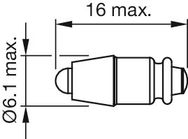
- Short Description:
- Single-LED, T1 ¾ MG, Red, 12 V AC/DC +10%
- Kind of iIllumination:
- Single-LED
- Hints:
- Due to high surface temperatures, the series resistor must not be soldered directly to the terminals of the equipment (use a terminal plate)When using AC/DC types with AC operation, slight flickering can occurThe luminous intensity stated is for when used with DCElectrical and optical data are measured at 25 °CThe specified versions are built with a protection diode (halve wave rectifier) in series and the LEDLuminosity and wave length variations caused by LED manufacturing processes may cause slight differences regarding the illumination. The customer has to decide what resistor shall be used to the LEDWhere supply voltages are over 48 V, a voltage-reduction element (external protective series resistor) must be used.Keep to the country specific safety instructions
- Wiring diagrams:
- Dimension drawings:
파일 다운로드
어디서 구입할 수 있나요?
장바구니에 담기