
귀사의 제품:

기계적 특성
- Terminal:
- PCB terminal
- Weight:
- 0.005 kg
증명서
- REACH:
- REACH compliant
- RoHS:
- RoHS compliant
기타
- Short Description:
- Lamp element, PCB terminal, Plastic
- Material:
- Plastic
- Housing material:
- Plastic
- Hints:
- Including locking pin
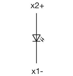
- Wiring diagrams:
- Component layouts:
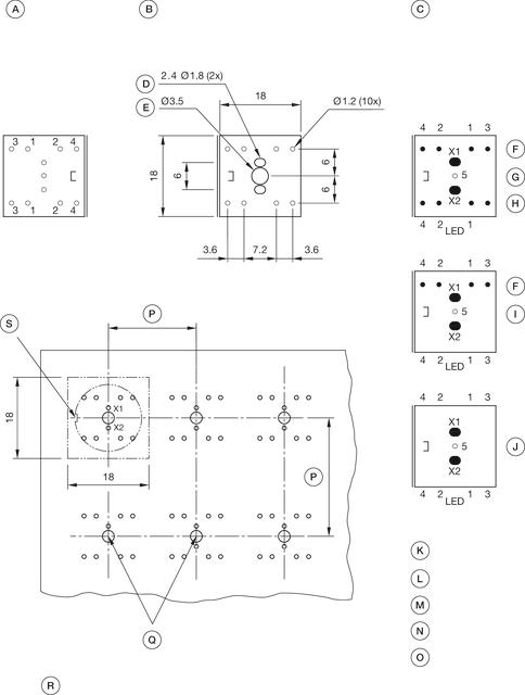 A = Terminals (rear side)
B = Drilling plan (component side)
C = non-metallic
D = Cu-Pad
E = Occupancy plan (component side)
F = 1. Switch
G = Switching element 2 Normaly close + 2 Normaly open, Part No. 71-672.026
H = 2. Switches
I = Switching element 1 Normaly close + 1 Normaly open, Part No. 71-671.026
J = Illumination element, Part No. 71-670.026
K = X1 Lamp cathode (-)
L = X2 Lamp anode (+)
M = 1-2 Contact normally closed
N = 3-4 Contact normally open
O = 5 Hole for interlocking pin
P = Front dimension min.
Q = Position interlocking pin
R = Note:
Pitch of the print circuit board hole Ø3.5 must agree with the mounting holes on the front plate
S = Slot in actuator
파일 다운로드
장바구니에 담기