Assembly settings
정면
Front form
Round
Round
선택하다 ...
장착
Mounting type
Panel mounting
Panel mounting
선택하다 ...
작동/표시 부분
Lens illumination
Illuminated
Illuminated
선택하다 ...
전기적 특성
Contacts
1 NO
1 NO
선택하다 ...
Switching rating
42 V @ 0,1 A
42 V @ 0,1 A
선택하다 ...
기계적 특성
Terminal
Universal terminal, 2 x 0.5 mm
Universal terminal, 2 x 0.5 mm
선택하다 ...
Switching system
Low-level element
Low-level element
선택하다 ...
Contact material
Gold
Gold
선택하다 ...
Switching action
Maintained
Maintained
선택하다 ...
주변 환경
IP front protection
IP67, according to DIN EN 60529
IP67, according to DIN EN 60529
선택하다 ...
뒤로

귀사의 제품:

정면
- Front form:
- Round
장착
- Mounting type:
- Panel mounting
작동/표시 부분
- Lens illumination:
- Illuminated
전기적 특성
- Switching voltage and switching current:
- 100 mA at 42 VAC/VDC
- Contacts:
- 1 NO
- Switching rating:
- 42 V @ 0,1 A
- Electric strength:
- 3000 VAC, 50 Hz, 1 min. between all terminals and earth, according to EN/IEC 61058-1
- Protection class:
- ll
기계적 특성
- Terminal:
- Universal terminal, 2 x 0.5 mm
- Contact material:
- Gold
- Switching action:
- Maintained
- Switching system:
- Low-level element
- Switching system:
- This low-level switching element was designed for switching low powers in electronic circuits. The mechanism assures reliable switching of loads ranging from a few μA/μV up to 100 mA/ 42 VAC/DC.Single-break momentary contact, as normally open or normally closed with 4 independent points of contact. 2 momentary contactsper switching element; combination of normally open and normally closed is possible.Special features are the long life, extremely short rebound time and stable contact resistance.
- Mechanical lifetime:
- 1 Mil. cycles of operation
- Operating force:
- 3 N … 4 N, depending on the number of switching elements
- Operating Travel:
- 3 mm
- Tightening torque:
- Fixing nut max. 0.25 Nm
- Terminal details 1:
- The universal terminals permit these units to be mounted on printed circuit boards (PCB). These terminals can also be used as soldering or plug-in terminals.For these terminals we can also supply a plug-in base which, when soldered on to the board, enables the switch to be plugged in.
- Wire cross section:
- Max. wire diameter 2 wires of 1 mmMax. wire cross-section of stranded cable 2 x 0.75 mm²
- Weight:
- 0.016 kg
주변 환경
- IP front protection:
- IP67, according to DIN EN 60529
- Operating temperature:
- – 25 °C … + 55 °C, mounted as a block, make sure the heat can escape freely
- Storage temperature:
- – 40 °C … + 85 °C
- Shock resistance:
- Max. 150 m / s², pulse width 11 ms, 3-axis, (semi-sinusoidal as per EN IEC 60068-2-27)
증명서
- Conformities:
- 2011 / 65 / EC (RoHS), 2014 / 35 / EU (LVD)
- REACH:
- REACH compliant
- RoHS:
- RoHS compliant
기타
- Short Description:
- Actuator, Illuminated, Round, 1 NO, Maintained, Universal terminal, 2 x 0.5 mm, IP67, according to DIN EN 60529
- Housing colour:
- Black
- Wiring diagrams:
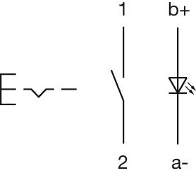
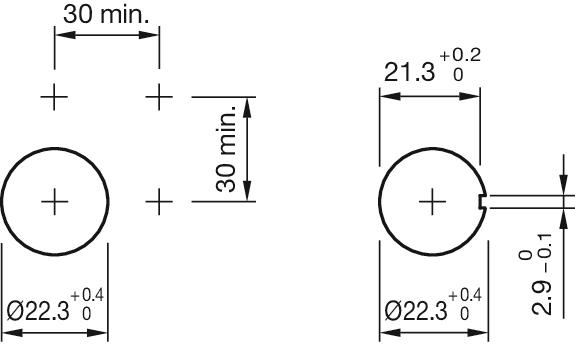
- Component layouts:
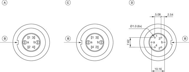 A = Terminals (rear side)
B = Anti twist device
C = Diode block
D = Drilling plan (component side)- Mounting cut-outs:
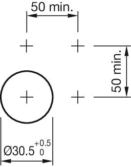
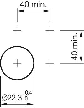

- Dimension drawings:
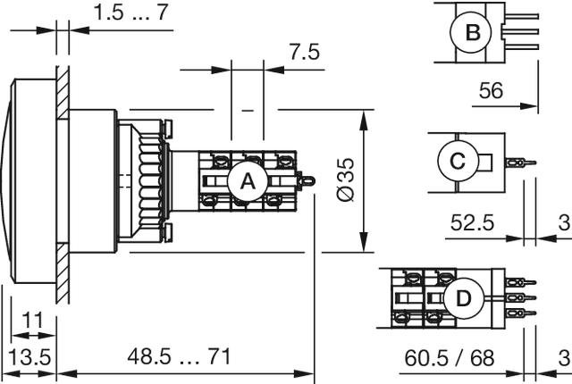 A = Solder terminal
B = Plug-in terminal 2.8 x 0.5 mm
C = Universal terminal 2.0 mm x 0.5 mm
D = Universal-Solder terminal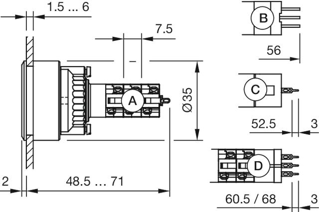 A = Solder terminal
B = Plug-in terminal 2.8 x 0.5 mm
C = Universal terminal 2.0 mm x 0.5 mm
Universal-Solder terminal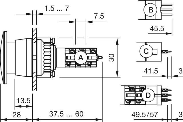 A = Solder terminal
B = Plug-in terminal 2.8 x 0.5 mm
C = Universal terminal 2.0 mm x 0.5 mm
D = Universal-Solder terminal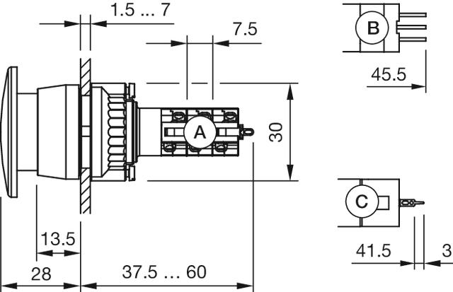 A = Solder terminal
B = Plug-in terminal 2.8 x 0.5 mm
C = Universal terminal 2.0 mm x 0.5 mm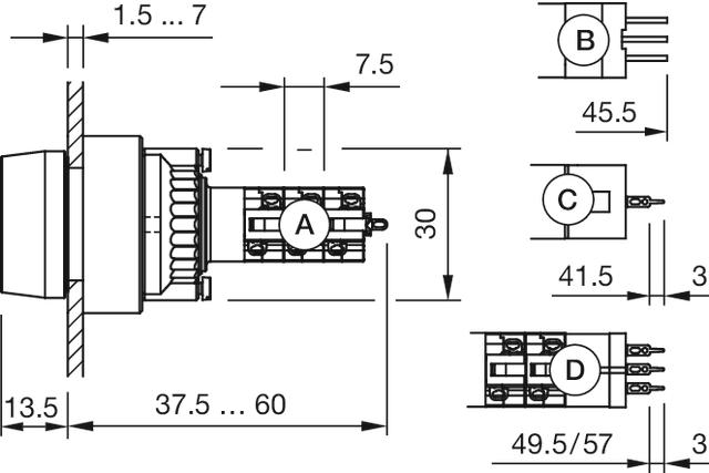 A = Solder terminal
B = Plug-in terminal 2.8 x 0.5 mm
C = Universal terminal 2.0 mm x 0.5 mm
D = Universal-Solder terminal
파일 다운로드
장바구니에 담기